Here are a list of Tips & Suggestions found throughout the VisualCAM-MESH help system:
 Abrupt changes in Curvature: Use Curvature and Reflection Lines to show abrupt changes in facet curvature tangents on your mesh model. If unwanted curvatures or protrusions are found, try using the Smooth and Re Mesh commands and then analyze your mesh again to see the difference in curvature results. Abrupt changes in Curvature: Use Curvature and Reflection Lines to show abrupt changes in facet curvature tangents on your mesh model. If unwanted curvatures or protrusions are found, try using the Smooth and Re Mesh commands and then analyze your mesh again to see the difference in curvature results.
Imported Point Cloud Data: The Curvature method is useful for analyzing mesh models created from imported point cloud data! Refer to the Create Mesh from Point Cloud command for more information.
Analyze before Printing: It is ALWAYS a good idea to use these Analysis techniques before sending your mesh model to the 3D printer. They can reveal areas of concern that can be fixed, saving you valuable time and money!
|
|
When using Mesh Boolean Operations: If any selected mesh does not form closed volume (i.e., there are any open edges) the Mesh Boolean operations (i.e., Unite, Subtract or Intersect) will fail. This can sometimes occur with imported data files. If this occurs, use the VisualCAM Auto Fix command on each mesh before using the Unit, Subtract or Intersect Mesh commands. You can also use the VisualCAM Diagnose command to check for mesh errors.
|
|
Tips for Repairing your Mesh: VisualCAM-MESH provides tools to allow you to fix and repair many irregularities in your mesh models, saving you valuable time and money! Stitch & Close can fix "cracks" along mating facets and close open meshes. Auto Fix can do the same and more including fixing any incorrectly oriented facets. Reduce, Re-mesh and Smooth can fix a variety of irregularities. Diagnose can check and fix edges, triangles and vertices. Check can verify that your mesh model is positioned correctly for your selected 3D printer.
|
|
Use Slice to Check your Mesh: After the Slice object is created, select it from the Data Tree and the Browser (see below) will report the total number of gaps (if any) that are encountered by each slice. You can fix gaps in your mesh model using the Auto Fix or the Diagnose commands.
|
|
Using Offset Mesh: If you receive the message "Terminated due to error" when using the Offset command, here are some things to look at:
1.The mesh you have selected for offset may not be closed. Try using the Auto Fix command first, to close it. 2.Your Tolerance may need to be adjusted. Ideally the Tolerance should be 1/10th of Offset Distance. For example, if the Offset Distance is set to 0.1, the Tolerance needs to be a value of 0.01 or lower (i.e., a tighter tolerance).
Tightening up the tolerance may increase the computation time depending on the complexity of the geometry. |
|
Re-meshing Tips: If your mesh contains self-intersections, this could result in gaps in the mesh when the Re-Mesh command is performed. It is always a good practice to use Auto Fix to clean-up the mesh, fixing any self-intersections before re-meshing.
|
|
Using Offset Mesh: If you receive the message "Terminated due to error" when using the Offset command, here are some things to look at:
1.The mesh you have selected for offset may not be closed. Try using the Auto Fix command first, to close it. 2.Your Tolerance may need to be adjusted. Ideally the Tolerance should be 1/10th of Offset Distance. For example, if the Offset Distance is set to 0.1, the Tolerance needs to be a value of 0.01 or lower (i.e., a tighter tolerance).
Tightening up the tolerance may increase the computation time depending on the complexity of the geometry. |
|
Using Point Cloud Data: It is highly recommended that you use the Inspect & Modify tools to check a mesh resulting from point cloud data. You can use the Repair Tools to fix any gaps or missing facets attributed to faulty point cloud data.
|
|
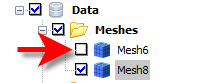
Viewing a Negative Offset Mesh: A mesh resulting from a negative offset value will be "hidden" within the volume of the selected mesh. To view the new mesh in the graphics window, uncheck the selected mesh from the Data Tree in the Browser.
|
|
|
When Converting a Mesh from a Shell: First determine the lowest degree of accuracy that you can accept in your 3D printed part. Then adjust the Faceting Tolerance accordingly to reduce model size, file size and 3D printing time.
|
|
Working with Assemblies: The Separate command is useful for separating multiple components of an assembly that were imported as a single mesh object.
Disconnecting Meshes: If you used the Convert Mesh from Shell command and selected multiple disconnected shells you can use this command later to "disconnect" them.
Using the Split Command: If you want to "break" a connected mesh into multiple segments to 3D print separately, use the Split command.
|
|