This command can be used to Manipulate individual facets on your mesh using a graphical manipulator. Various options are provided for selecting the area to manipulate. Once the Manipulator is displayed you can use it to transform along or rotate about the three principal axis displayed. Dynamic feedback is provided prior to committing the change.
 This command will change the shape of your mesh model!: Experimentation with the methods and options listed below is advised until you understand and are satisfied with your results. This command will change the shape of your mesh model!: Experimentation with the methods and options listed below is advised until you understand and are satisfied with your results.
|
1.First the mesh and then vertices on the mesh are selected for modification. Various selection methods are provided. 2.The Manipulator is then placed on a vertex and used to graphically manipulate the selected area dynamically. 3.The change is then applied and the mesh is updated. |
|
Screen Pick
|
Optional Information
|
Step 1
|
Select the mesh you want to modify and then press Enter or Right-click. You can select from the graphics window or from the Browser.
|
You can select a mesh first and then select the command icon.
|
Step 2
|
From the Command Dialog, choose one of the available options to select those vertices on the mesh that you want to manipulate. See Manipulator Options below.
|
See below.
|
Step 3
|
Select the Place manipulator button and then pick one of the selected vertices. The Manipulator will display on the vertex.
|
See below.
|
Step 4
|
Use the Manipulator to transform and/or rotate the selected vertices. All of the selected vertices will be affected. The results are shown dynamically on the screen.
|
See below.
|
Step 5
|
Select the Finish and create new mesh button to accept the modifications.
|
-
|
|
Choose one of the following selection options from the Command Dialog to define the vertices on the selected mesh that you wish to manipulate. After the vertices are highlighted, pick the Place manipulator button and then pick the highlighted vertices to display the manipulator on them.
 Manipulator Options

Choose one of the following selection options from the Command Dialog to define the facet/vertices on the selected mesh that you wish to modify.
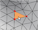
 The facets three vertices are selected. The facets three vertices are selected.
|
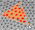
 All vertices within the polygon are selected for manipulation. All vertices within the polygon are selected for manipulation.
1.Left-click to pick start and end points for the polygon and then double-left-click to complete the polygon. Then left-click within the polygon to select the vertices contained within.
|
 All vertices within the polygon are selected for manipulation. Left-click to drag/pick the corners of the polygon. As the lasso surface area is widened, vertices within the lasso area are selected for manipulation. All vertices within the polygon are selected for manipulation. Left-click to drag/pick the corners of the polygon. As the lasso surface area is widened, vertices within the lasso area are selected for manipulation.
|
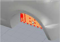
 All vertices lying on the surface are selected for manipulation. Select the planar surface and its vertices are selected. All vertices lying on the surface are selected for manipulation. Select the planar surface and its vertices are selected.
|
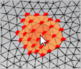
 All vertices lying within the painted area are selected for manipulation. Drag the cursor over the mesh painting an area and selecting vertices. All vertices lying within the painted area are selected for manipulation. Drag the cursor over the mesh painting an area and selecting vertices.
|
 You can enter a selection radius in the field provided. It will affect how many vertices are selected using each method listed above. You can enter a selection radius in the field provided. It will affect how many vertices are selected using each method listed above.
 Choose this icon to clear the current selection. Choose this icon to clear the current selection.
|
|
After facets are selected (using the Facet Selection Toolbar shown above), this button is used to place the Manipulator on a vertex. Once displayed, the Manipulator can be used to transform or rotate the selection. See Using the Manipulator below for more information.
") (a) |
") (b) |
") (c) |
The Manipulator displayed (a) on a single facet (b) on multiple facets (c) on a planar surface
|
|
Once the edits are made, choose this button to update the mesh.
|
The Manipulator is used to graphically rotate or transform the selected vertices of your mesh similar to using the Graphical Manipulator in VisualCAD.
The arrows displayed on the Manipulator can be selected and a numerical value placed to move the geometry in either X, Y or Z direction. Or the arrows can be selected and simply dragged in either the X, Y or Z direction.
To rotate the vertices, use the arcs displayed on the Manipulator. Each arc can be selected and a numerical value entered to rotate the vertices in either X, Y or Z direction. Alternately the arcs can be selected and simply rotated by dragging with the left hold of the mouse.
 Drag a Linear Axis |
 Drag a Rotational Arc |
 Enter translation Distance or Angle for rotation |
|
|
|