 Use this command to Slice your mesh model at controlled intervals along the C-Plane orientation. This command is useful for previewing slice profiles prior to 3D printing. You can control the slicing using a depth vale or by entering the total number of slices to create. If any gaps are encountered they are reported in the VisualCAM Browser when the resulting Slice object is selected.
 Understand that the Slice object is for visual purposes only. If you want to use the slice(s) as curve geometry, use the Export Slice command. Understand that the Slice object is for visual purposes only. If you want to use the slice(s) as curve geometry, use the Export Slice command.
|
|
Screen Pick
|
Optional Information
|
Step 1
|
Select the Slice icon from the Model tab.
|
Steps 1 & 2 can be performed in reverse order. You can select a mesh first and then select the command icon.
|
Step 2
|
Select the mesh you want to slice and then press Enter or Right-click. You can select from the graphics window or from the Browser.
|
Step 3
|
From the command dialog, select which Slice Parameter you wish to use (Distance between... or Number of Slices).
|
-
|
Step 4
|
From the command dialog, select the Slice button to create the Slice object.
|
The Slice object is added to the Browser tree and displayed in graphics window.
|
|
The following Cut Depth Control parameters are available:
 Optional Slice Parameters Distance between each slice
Select this method and specify the distance between each slice. The first cut will begin at the C-Plane.
•Number of Slices
Select this method and enter the total number of slices to create. The first cut will begin at the C-Plane. •Slice
Pick this button to create the Slice object. It is added to the Data Tree and displayed in graphics window. |
 Use Slice to Check your Mesh: After the Slice object is created, select it from the Data Tree and the Browser (see below) will report the total number of gaps (if any) that are encountered by each slice. You can fix gaps in your mesh model using the Auto Fix or the Diagnose commands. Use Slice to Check your Mesh: After the Slice object is created, select it from the Data Tree and the Browser (see below) will report the total number of gaps (if any) that are encountered by each slice. You can fix gaps in your mesh model using the Auto Fix or the Diagnose commands.
|
|
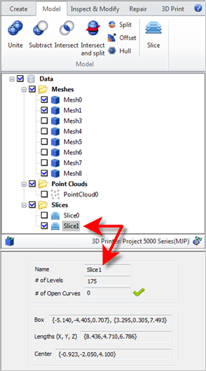
Once created, a Slice object is added to the Browser. Selecting it from the Data Tree will show its Name, # of Levels and # of Open Curves (if any) as well as the entire model extents (Box, Lengths and Center) in the Information Window.
If ANY open curves are generated, the open curves are generated, the  icon is displayed indicating that your mesh is NOT closed. If the mesh is closed, the icon is displayed indicating that your mesh is NOT closed. If the mesh is closed, the  icon is displayed. icon is displayed.
|