Available in: |
Xpress |
Standard |
Expert |
Professional |
Premium |
Note: Continuous 5 Axis operations are only supported in the Premium configuration
In order to perform an index 5 Axis Operation, you first need to orient the Machine Coordinate System. This is done using the Set CSYS Setup operation. The Machine Coordinate System is the coordinate system that defines the tool orientation. The zero position is then set using Set Work Zero operation. This can then be followed by any of the allowable 3 axis machining operations, thereby allowing access to the part from different orientations. Additional information on Set CSYS Setup can be found at - Setup.
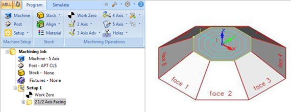
The example below shows steps for creating a 5-axis index toolpath for the octagon model. By default Setup 1 (Set CSYS Setup) is oriented to the WCS and the origin is located at the WCS origin. 1. Create Work Zero operation from Program tab and using the pick option set the X Y Z origin to 0,0,0 2. Generate a 2½ Axis Facing toolpath by selecting the Flat Area or curve region from the top face of the part.
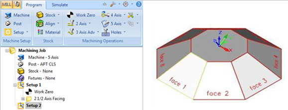
3. Create a new Setup using Set CSYS Setup and under Align to Geometry use Select Surface and pick Face 1 and Click OK. You will now notice the Machine Coordinate system oriented to Face 1. Note: If you need to move the origin, create a Work Zero operation.
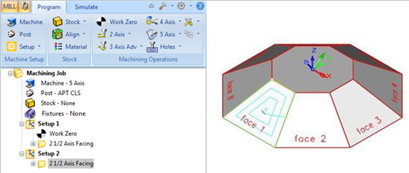
4. Generate a 2½ Axis Facing toolpath by selecting the region at Face1.
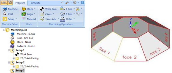
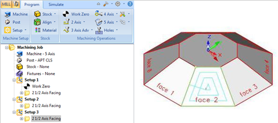
5. Create a new Setup using Set CSYS Setup and under Align to Geometry use Select Surface and pick Face 2 and Click OK. You will now notice the Machine Coordinate system oriented to Face 2. Note: If you need to move the origin, create a Work Zero operation.
6. Generate a 2½ Axis Facing toolpath by selecting the region at Face2.
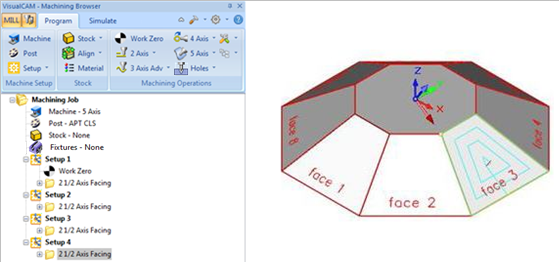
7. Repeat the above steps for other faces.
|
