Available in: |
Xpress |
Standard |
Expert |
Professional |
Premium |
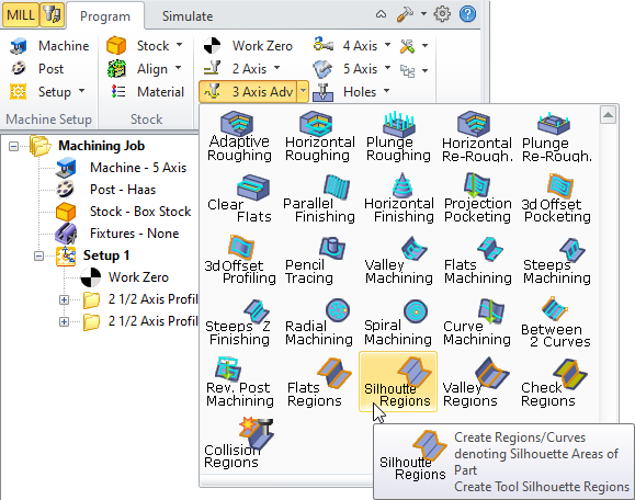
![]() The silhouette regions are used to compute the contact regions based on the selected tool and the visible part geometry. The system will compute the regions where the tool can safely traverse in such a way that the entire part geometry can be machined using the computed region geometry. Silhouette regions can also be thought of as the Tool Contact Area Regions.
The silhouette regions are used to compute the contact regions based on the selected tool and the visible part geometry. The system will compute the regions where the tool can safely traverse in such a way that the entire part geometry can be machined using the computed region geometry. Silhouette regions can also be thought of as the Tool Contact Area Regions.
|
An example of this is shown below. The surface shown below represents the part geometry to be machined.  Example surface represents the part geometry to be machined The computed tool silhouette area regions are shown displayed in red, below:  The computed tool silhouette area regions are in red Now these regions can be selected in subsequent machining operations to compute toolpaths that will completely traverse the part surface to be machined. An example of a toolpath utilizing these computed regions is shown below.
 The toolpath using computed tool silhouette area regions |