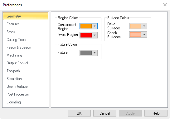
You can set the colors to display various objects using this dialog. To change each of the color settings in this dialog select the colored button next to the item of interest. This will bring up the color selection dialog, which can be used to choose the color needed. Once a color has been selected the button will change its color to the selected one.
 CAM Preferences > Geometry |
Containment Region Use this color selector to set the display color for Containment Regions (i.e., your Control Geometry). Avoid Region Use this color selector to set the display color for Avoid Regions (i.e., your Control Geometry). |
Drive Surfaces Use this color selector to set the display color for Drive Surfaces (5 Axis). Check Surfaces Use this color selector to set the display color for Check Surfaces (5 Axis). |
Fixture Use this color to represent fixture geometry. |