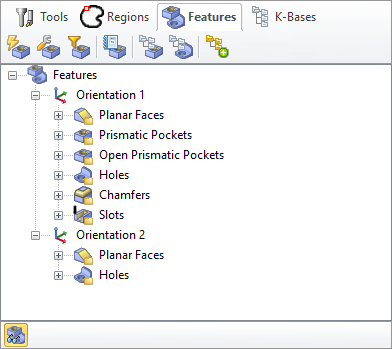
Selecting the Features tab under the Machining Objects Browser displays the Feature Manager. It allows you to create and work with detected features from your 3D solid model. See Understanding Feature Machining in VisualCAM for important information about Machining Features.
Note: See Right-Click Commands for a complete list of all right-click commands available from the Machining Operations (Mops) Browser and the Machining Objects (Mobs) Browser.
 Important: Machining Features can ONLY be extracted from poly-surface models (i.e., solid models). If your part model is not a solid, you must "stitch" all surfaces into a poly-surface prior to Creating Machining Features! Important: Machining Features can ONLY be extracted from poly-surface models (i.e., solid models). If your part model is not a solid, you must "stitch" all surfaces into a poly-surface prior to Creating Machining Features!
|
 The Machining Objects (MObs) Browser, Features Tab |
Summary
|
Available Configuration
|
Xpress
(XPR)
|
Standard
(STD)
|
Expert
(EXP)
|
Professional
(PRO)
|
Premium
(PRE)
|
Features tab Command Icons
|

|
-
|

|

|

|

|
Performs Automatic Feature Detection (AFD) from your part model based all possible machining Orientations. See Automatic Feature Detection (AFD) for more information.
|

|
-
|
-
|

|

|

|
Performs Interactive Feature Detection (IFD) by selecting a face from your part model to define the machining Orientation. See Interactive Feature Detection (IFD) for more information.
|

|
-
|

|

|

|

|
Allows you to Set Filters for Feature Detection so that only certain feature types or hole diameters are detected. See Set Filters for Feature Detection for more information.
|

|
-
|

|

|

|

|
Allows you to list all of your detected features. See List Features for more information.
|

|
-
|

|

|

|

|
Allows you to setup a features knowledge base. See: Setup Features Knowledge Base.
|

|
-
|

|

|

|

|
Allows you to create a hole feature machining operation. See: Create Hole Feature Machining Operation.
|

|
-
|

|

|

|

|
Allows you to perform Automatic Feature Machining (AFM) based on the default (AFM) Knowledge Base defined in the Features section of the CAM Preferences dialog. See Automatic Feature Machining (AFM) for more information.
|
Features tab Toolbar Icons
|

|
-
|

|

|

|

|
This icon Toggles the display of Features in the drawing window. It is located at the bottom of the browser when the Features tab is active.
|
|
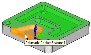
After you have performed either AFD or IFD on your part model, you can move the cursor over a part feature and its identification name will display. This is the name created for the feature and listed in the Features tree.
 Feature Identification on Cursor Highlight |
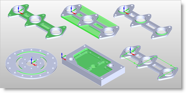
The feature types recognized are listed in the table below:
Feature Types Detected
|
 Hole |
 Prismatic Pocket |
 Open Prismatic Pocket |
 Boss |
 General Pocket
(3 Axis) |
 Slot |
 Open Slot |
 T-Slot |
 V-Slot |
 Open General Pocket
(3 Axis) |
 Planar Face |
 Fillet |
 Chamfer |
 Stepped Prismatic Pocket |
 Silhouette |
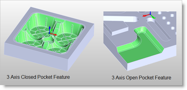
 Some 2 Axis Feature Examples  Some 3 Axis Feature Examples |


