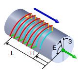
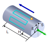
The following Cut Parameters tab allows you to define the cut parameters for the current 4 Axis Parallel Finishing operation. You can set Global Parameters, Cut Pattern, Axial Containment and Stepover Control parameters via this tab of the operation dialog. The Global Parameters section allows you to set the tolerance value to be used in machining. A uniform thickness or stock that needs to be left around the part can also be specified here. Refer to each option below.
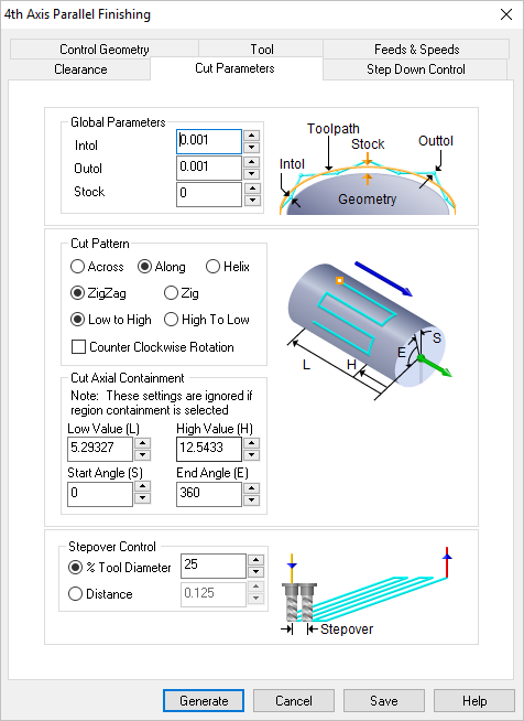 Dialog Box: Cut Parameters tab, 4th Axis Parallel Finishing Operations |
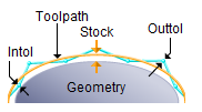 Global Parameters, 3 Axis Operations The Global Parameters section allows you to set the tolerance value to be used in machining. Intol and Outol are allowable deviations (tolerances) from the actual part geometry plus the Stock layer (if any). A uniform thickness or stock that needs to be left around the part can be specified here. Intol / Outol
Stock |
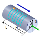
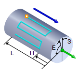
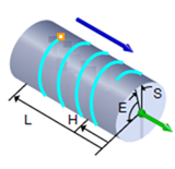
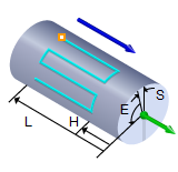
This section allows you to define the type of cut pattern that will be generated. You can also contain the toolpath both by specifying low and high values along the cut axis as well as by specifying a low and a high angular values about the rotation axis. Across Axis / Along Axis / Helix Selecting Along Axis will create toolpaths that traverse along the rotation axis. Selecting Across Axis will generate toolpaths that traverse perpendicular to the rotation axis. Selecting Helix will create toolpaths in a helical pattern around the part. The Stepover Control (see below) determines the helical pitch.
ZigZag / Zig Selecting ZigZag will allow the toolpath to traverse back and forth while the Zig option will force the toolpath to be in one direction only.
Low To High / High To Low Selecting Low To High will make the toolpath start from the lower coordinate along the tool axis and proceed to the higher coordinate. Selecting High To Low will reverse this behavior.
Counter Clockwise Rotation
|
You can also contain the toolpath both by specifying Low Value (L) and High Value (H) values along the cut axis as well as by specifying a Start Angle (S) and End Angle (E) values. The location of the Cut Containment planes are displayed in the graphics window. Note that these settings are ignored if machining regions are selected using the Control Geometry tab of the dialog. 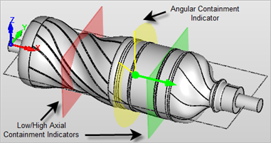 Cut Containment Indicators Low Value (L) / High Value (H) Entering values for these two settings will contain the cutting within these two locations. Cutting will not be perform below the Low Value (L) location or above the High Value (H) location. These distances are measured from the MCS and along the rotation axis. Refer to the illustrations above. Start Angle (S) / End Angle (E) Entering values for these two settings will contain the cutting within these two locations. Cutting will not be perform below the Start Angle (S) and above the End Angle (E) positions. These angles are measured from the MCS and about the rotation axis. Refer to the illustrations above.
|
 Stepover Control, 3 Axis Operations This allows you to define the spacing between the cuts. Select from the following options: % Tool Diameter Distance Scallop (not available for all operations) |

