In order to use machining regions in a machining operation, they must be first selected and made active. This can be done in several ways.
Here are the types of machining regions you can choose from: 1.Part Regions 2.Containment Regions 3.Surface Regions 4.Avoid Regions 5.Start Points |
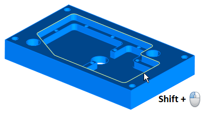
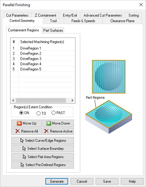
1.Select regions using the Select button on the menu bar. 2.Select regions graphically in the display window. 3.Select regions when creating or editing an operation from the Control Geometry tab of the operation's dialog box shown below using: Multiple Selections: Multiple regions can be selected by pressing the CTRL button. These selected regions can be used to create machining operations. The regions can be unselected using the None option (Select > None). Chain Selections: You can automatically select a chain of curves or edges by pressing the <Shift> key while performing a left-click selection. This works with any curves or edges that are connected end-to-end.  Chain Select (<Shift> + Left-click) More Information: Once a machining operation is created, new regions can be selected or existing regions can be removed from the operation as well. To edit the list of regions used in an existing operation, expand the folder corresponding to the machining operation in the Machining Browser window. Double-click on the Machining Regions icon. This will bring up the selected machining regions dialog. Now you can edit the list of regions using •Remove All to remove all the selected regions. •Move Up/Move Down - these allow you to move a selected Drive Region Up or Down in the list •Remove Active by selecting a region from the list of Selected Machining Region(s) •Select regions using the Select buttons on the menu bar. |
The display of the regions in the part file can be toggled on/off using the layer manager. |
VisualCAD allows you to save regions in an external ASCII file. Such a file can then be loaded into any part file to generate machining operations. To access the Export and the Import functions look under the File menu bar entry. |
 Dialog Box: Control Geometry Tab (Example) |