Once part geometry is loaded, you can use this command to change the orientation for turning. It can be invoked by selecting Part and Orient Part from Program tab under the Machining Browser. Note: This command changes the WCS orientation of your part. To change the MCS orientation use the Setup command.
 Machining Browser: Part, Orient Part |
 Dialog Box: Orient Geometry
Select the radio button representing the orthographic view of your part that you wish to machine. For example, select the right side radio button (on the positive X side in the dialog image) will rotate your part so that the positive X direction becomes the positive Z direction.
|
If your part is not aligned orthographically, you can use these options to align your part to selected geometry or active display element. Select from one of the options that will orient the part that you wish to machine:
Select Surface
 Choose the Pick button and then select a surface of your part to orient to. The part will be aligned such that the surface normal direction is aligned with the -Z axis. Choose the Pick button and then select a surface of your part to orient to. The part will be aligned such that the surface normal direction is aligned with the -Z axis.
Select Planar Curve
Choose the Pick button and then select a Planar Curve of your part to orient to. The part will be aligned such that the curve will be parallel to the XY plane (i.e., normal to the Z axis).
Align to Current View
Pick this button to align the part such as the Current View direction is aligned with the Z axis (i.e., you are looking in the -Z direction).
Align to Current C-Plane
Pick this button to align the part so that the Current C-Plane becomes parallel with the XY plane.
|
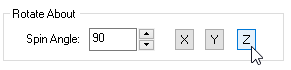
Use this option to Rotate About one of the principal XY or Z axis. Enter an angle and then select the button representing the axis you wish to Rotate About.
|
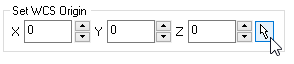
You can also independently set the coordinate location for the WCS. So for example, you can orient the part normal to a surface and then also choose a point on the surface to become the new WCS origin. In this case the part would be oriented to the surface while the point on the surface remains at the WCS.
|
|
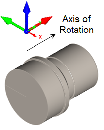
In TURN, the default rotational axis is along the X Axis of the World Coordinate System or WCS. Note: Once you select a direction and pick OK from the dialog, all of the geometry will be moved and/or rotated. In the example part shown below we want to orient the part so that the rotation axis is along the X Axis of the WCS. We also want the WCS origin to be located at the center of the back face of the part. Look at the steps below to see how it's done.
1.From the Program tab select Part and then Orient Part.
 Incorrect Orientation  Machining Browser: Part, Orient Part The dialog is displayed and the WCS is also displayed on the screen.
|
2.Under Rotate About, set the Spin Angle to 90 and then pick the Z button to rotate the WCS displayed on the screen. We want the X Axis of the WCS to point along the rotational axis of the part.
3.Now, let's locate the WCS origin. In the dialog under Set WCS Origin, select the Pick button.
4.Select the center point of the circular face of the back of the part. This is the face that will be mounted on the spindle of the lathe. When you select the point, the WCS triad is move to that point.
 Before  After |
5.Now pick OK from the dialog and the part is oriented as desired.
Before  After |
|