Here are the basic steps to define part geometry:
|
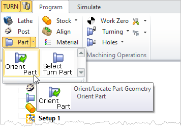
 Machining Browser: Part, Orient Part |
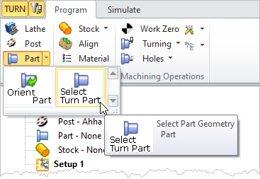
 Select Part (Select Part Geometry) under Program tab in Machining Browser |
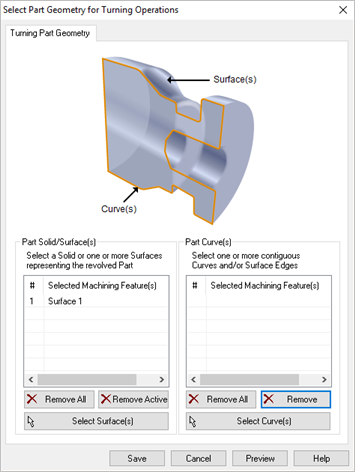
You can select surfaces or curves to define TURN part geometry.  Dialog Box: Select Part Geometry for Turning Operations |
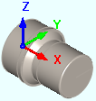
There are two lists on this dialog. Use one or the other to define the Turn Part (not both). If you have 3D geometry, pick the Select Surfaces button. You will be prompted to select part objects. Select the objects to define the part geometry and right-click or press Enter. If you only have a curve profile, make sure it is located in the positive XZ plane. See Part Geometry Types for more information. The selected geometry is listed under Selected Machining Feature(s) list. |
When the part is previewed, selecting Save defines the turn part geometry and displays Part-Defined under the machining browser. |
