Optimized machining is used when you want to maintain almost constant scallop height during machining with the Horizontal Finishing method. In this method, machining takes place in constant Z planes spaced a constant Z distance from each other. Due to this constant Z spacing, machining relatively flat areas will leave areas un-machined. The size of these un-machined areas increases with the degree of the flatness.
Optimized machining automatically recognizes these flat areas and inserts projection toolpaths, similar to 3 Axis Projection Pocketing to clean out un-machined areas. This is a highly effective way of maintaining almost uniform scallop height on the part. You have Stepover Control of the spacing of these optimized pocket toolpaths as well as Engage/Retract control for these pocket toolpaths. From the MecSoft Tech Blog: Optimized XY Machining.
Retracts are minimized when Optimized XY machining between levels is checked.
|
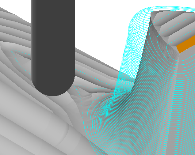 Optimized Machining Off
 Optimized Machining On |
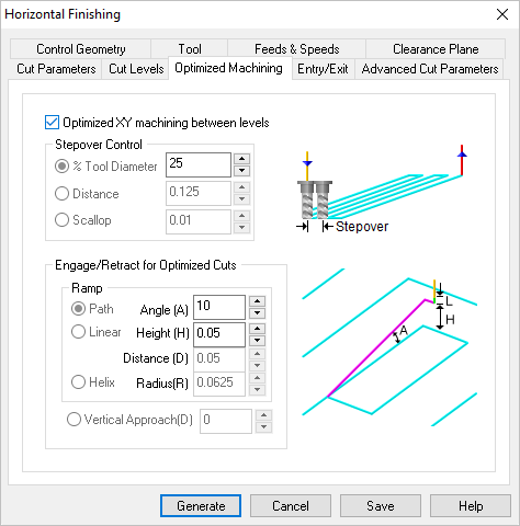 Dialog Box: Optimized Machining tab, Horizontal Finishing, 3 Axis |
Check this box to enable Optimized XY Machining between Levels and activate the following Stepover and Engage/Retract controls. |
 Stepover Control, 3 Axis Operations This allows you to define the spacing between the cuts. Select from the following options: % Tool Diameter Distance Scallop (not available for all operations) |
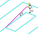
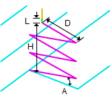
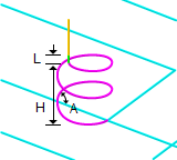
This section allows you to define how the cutter would engage into material when forced into such a situation. This can happen when machining a cavity or pocket. You have the option to Ramp the cutter or engage in a Vertical Approach (D). The ramp engage motion will typically be used when machining with a flat or corner-radius end mills. In the ramp option, the cutter can ramp in one of the following 3 ways:
Path In this method the cutter follows the contour of the part in a Ramping motion on the outside until it hits the cutting start point. You can control the angle of descent and the length of this engage motion by specifying these parameters. Enter the Angle (A) and Height (H). Enter the Angle (A) and Height (H). Ramp height between levels is set automatically based on depth of cut. The tool ramps from the previous cut level if you set a ramp height smaller than the distance to the previous level. Linear Here the cutter follows a linear ramp motion, Ramping back and forth from a user specified height to the engage point. The length of this move, as well as the angle of this motion can be specified. Enter the Angle (A), Height (H) and Distance (D). Helix Here the cutter follows a helix as it descends from a user-defined height to the first cut point. The angle of the helix as well as the radius of the helix can be specified. Enter the Angle (A), Height (H) and Radius (R). Vertical Approach (D) Setting the Engage/Retract in material to Vertical approach applies a vertical plunge into the material. 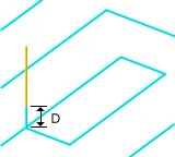 Vertical Approach (D) |
