VisualCAM includes many toolpath operation types to choose from depending on your software configuration. Also each operation type has default parameters predefined to allow you to quickly create a toolpath and view the results.
Here are the basic steps to create a toolpath:
1.Open a part or drawing file or create the geometry that your wish to create a toolpath for. 2 Axis operations can be created with 2D or 3D geometry. 3 Axis operations require surface and/or mesh geometry. Some 4 Axis operations require 3D solids or surfaces only. All and 5 Axis operations require 3D solids or surfaces only. You must have visible geometry in your part file to create a toolpath.
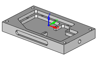
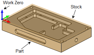
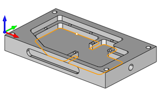
In this example we will generate a 2 Axis Pocketing toolpath to machine the bottom pocket in this 3D solid model.
|
2.Perform the steps needed to setup your part. These include defining your Machine, Post and Stock. You must first have geometry and Stock defined to create a toolpath.
|
3.Select the Program tab.
 MILL Module shown, Similar for MILL-TURN, TURN and Profile-NEST |
4.Decide what type of toolpath to create and select the operation type from the menus on the Program tab. Depending on your software configuration, you can select from the 2 Axis, 3 Axis, 4 Axis or 5 Axis menus. The operation dialog for that toolpath type will display.
5.![]() For this example we will generate a 2 Axis Pocketing toolpath so select the 2 Axis menu.
For this example we will generate a 2 Axis Pocketing toolpath so select the 2 Axis menu.
6.![]() Select Pocketing from the menu to display the dialog.
Select Pocketing from the menu to display the dialog.
|
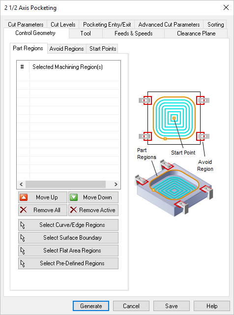
7.The dialog has several tabs at the top. The Control Geometry tab is displayed first. Use it to select your machining regions. All 2 Axis operations require that you select machining regions. In 3 Axis and 4 Axis operations machining regions are used to if you want to contain the toolpath but are not required for all 3 and 4 Axis operations. 5 Axis operations do require machining regions.
8.The buttons on this tab are used to select your machining regions. Here we will pick the Select Flat Area Regions button.
|
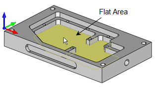
9.The dialog minimizes and you are prompted to select a flat area. We select the bottom of the inner pocket and then right-click or press <Enter>.
|
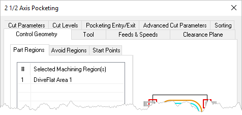
10.The dialog reappears with the selected machining regions listed. They are also highlighted on the part.
There are other ways to define and select machining regions. You can pick Help from the dialog to learn about each button option. |
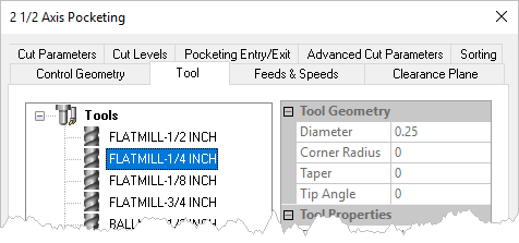
11.Select the Tools tab and select a tool from the Tools list or select the Edit/Create/Select Tool ... button to create a tool. You must select a tool to create a toolpath.
|
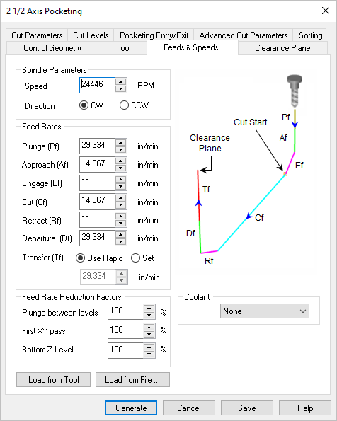
12.Select the Feeds & Speeds tab and set the Spindle Speed and Feed Rates for the operation and use the Load from Tool ... or Load from File ... buttons. The Load from File ... button displays the Feeds & Speeds Calculator to assist you will selecting feeds and speeds values for the operation.
|
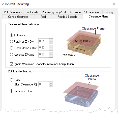
13.Select the Clearance Plane tab and adjust if desired.
|
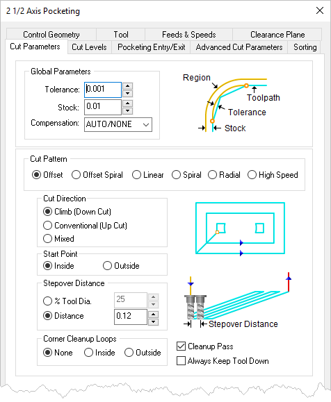
14.Now we will select the Cut Parameters tab of the dialog and make the following adjustments. Stock will leave 0.01 remaining on the side walls. The cut pattern will offset the perimeter of the pocket. The cut will start in the middle of the pocket, offset outward at a step over 0.01 and perform a cleanup pass at each cut level.
Tolerance : 0.001
Stock : 0.01
Cut Pattern : Offset
Cut Direction : Climb
Start Point: Inside
Stopover Distance : 0.12
Corner Cleanup Loops : None
Cleanup Pass : Checked
|
15.Next we select the Cut Levels tab. All 2 Axis operations require your to adjust the Cut Levels tab to control the depth of cut. In all 3, 4 and 5 Axis operations your part surfaces will limit the maximum depth of cut.
|
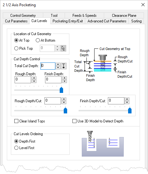
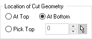
16.First make a selection to define the Location of Cut Geometry. In our example we select At Bottom because the machining regions we selected lie at the bottom of the pocket. If they lie at the top we would select At Top. If they do not lie either at the top or the bottom of the pocket you can use the Pick Top option to define the top of the cut.
|
17.Next we move to the Cut Depth Control section. If you know how deep the pocket should be just enter the depth in the Total Cut Depth field. This is always an absolute value (i.e., no negative numbers).
|
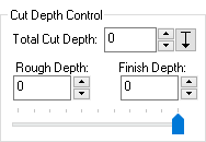
18.![]() In our case we do not know the exact depth without manually measuring the geometry so we will select the Pick button.
In our case we do not know the exact depth without manually measuring the geometry so we will select the Pick button.
19.The dialog minimizes and prompts us to select s start point and an en end point to define the Total Cut Depth. We select the top and bottom floor of the pocket and then right-click or press <Enter>.
|
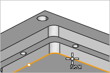
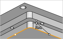
20.The dialog reappears with the Depth of Cut calculated for us.
|
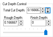
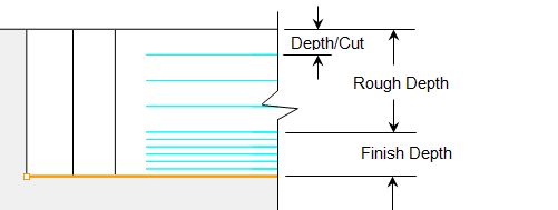
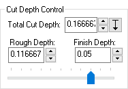
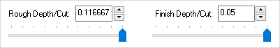
21.Notice that the value in the Rough Depth field is now the same as the Total Cut Depth. You have the option to split the Total Cut Depth into a Rough Depth and a Finish Depth. We will enter 0.05 into the Finish Depth field and then press the <Tab> key (or simply activate another field.
22.We see that the Rough Depth value is now reduced by 0.05. The Rough Depth and Finish Depth values will always equal the Total Cut Depth value. You can also use the slider to split these values up.
|
23.You will also notice now that the Rough Depth/Cut and Finish Depth/Cut fields are populated with the save values. If we generate the pocket toolpath right now, there would be one rough level cut and one finish level cut.
|
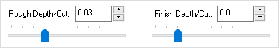
24.We can add additional cut levels by entering 0.03 in the Rough Depth/Cut field and entering 0.01 in the Finish Depth/Cut field. This will produce 4 rough cut levels at the top of the pocket and 5 finish cut levels at the bottom of the pocket.
|
25.With our cut levels defined we select the Pocket Entry/Exit tab of the dialog.
|
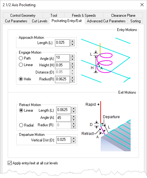
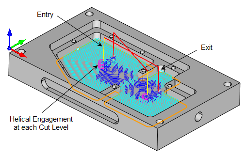
26.Now we select the Pocketing Entry/Exit tab to control how the cutter will enter and exit the part and make the following selections:
Approach Motion Length (L) : Default (0.025)
Engage Motion : Helix
Helix Radius (R): Default (0.0625)
Retract Motion : Linear, Length: 0.0625, Angle (A): 45
Departure Motion : Vertical Distance (D): Default (0.025)
Apply entry/exit at each cut level : Checked
|
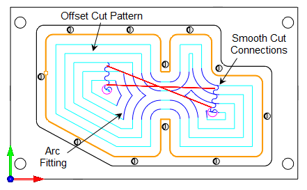
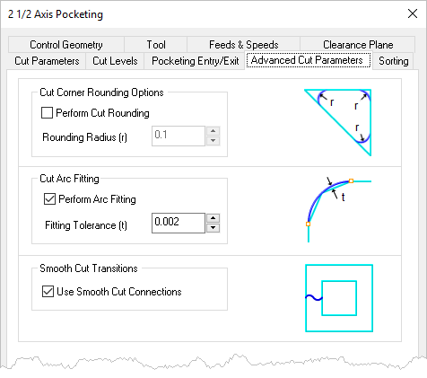
27.Now we will select the Advanced Cut Parameters tab and make the following selections. The parameters available on this tab will depend of the type of toolpath operation and your software configuration.
Perform Arc Fitting : Checked
Fitting Tolerance (t) : 0.002
Use Smooth Cut Connections : Checked
With these selections full and partial arc motions will be generated within the Fitting Tolerance (t) we have specified. There will also be smooth cut connections between step over paths. These advanced parameters will reduce the torque stress on your CNC machine and also reduce tool deflection, prolonging tool life. |
28.Since we only have one pocket we do not need to look at the Sorting tab.
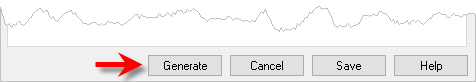
29.Now were ready! Select the Generate button at the bottom of the dialog to generate the 2 Axis Pocketing toolpath and display it on the screen.
|

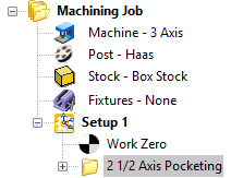
30.It is also listed in the Machining Job.
|
31.![]() If you do not see the toolpath displayed, select the Toggle Toolpath Visibility icon located at the bottom of the Machining Browser.
If you do not see the toolpath displayed, select the Toggle Toolpath Visibility icon located at the bottom of the Machining Browser.
32.Let's have a closer look at the toolpath.
|