This topic is intended for advanced users who are familiar with XML text editing and have administrative access to their Windows Operating System. VisualCAM has a built-in Feeds & Speeds Calculator that can suggest Spindle Speeds and Cut Feed Rates based on your stock material and active tool parameters!
However, what if you are cutting stock material that is currently not in our Materials Library? Or what if you don’t like what is currently assigned for the material of your choice in the Materials Library?
This topic will show you how to customize VisualCAM to add and manage multiple material files as well to add your own stock materials. If you are new to VisualCAM, you can review the topic The Feeds & Speeds Calculator.
First let’s review how material definitions are used in VisualCAM. From the Stock pane of the Program tab in the Machining Browser you will find the Material icon. Selecting it will display the Select Stock Material dialog. Here you can select a stock material from the Material File. If there is an associated Material Texture file, then this texture is assigned to the stock model and rendered in the graphics window. This texture rendering on the stock can be toggled on or off using the Material Texture Visibility icon, located at the base of the Machining Browser.
Also, from the Feeds & Speeds tab on the Create/Select Tool dialog you can select Load from File to display the Feeds & Speeds Calculator dialog. The Material selection in this dialog will default to the stock Material you have previously selected from the Select Stock Material dialog (shown above). |

The Material selections available to you from these dialogs are retrieved from a Feeds & Speeds XML file installed with the program. There are separate files for INCH and METRIC units. The files are located in the \Materials folder of the ProgramData install path of the program. Here is an example: C:\ProgramData\MecSoft Corporation\Program Name & Version\Materials.
|
You can create your own Material Files and store them in the default folder. The CAM system on startup will load all material files in the folder specified in the dialog above as long as the units of the material files match the part units that you are working with. If the system finds multiple material files with matching units, it will populate the drop-down control in the Materials dialog allowing you to select a specific material file to suit your needs.
Having multiple material files can help manage different materials and associated feeds & speeds data without having to cram all of the data into one file. In addition, multiple material files may be useful if you have multiple machines in the shop with different power capabilities and you want to use different feeds and speeds settings per machine. Under this scenario you could have one material file per machine saved in the default folder and load the correct material file depending on which machine you are programming toolpaths for. |
Material files can be edited to customize the data stored in these files to suit your shop needs.
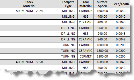
Here are the steps required to add new material definitions. Be sure to read these steps carefully: 1.Make a backup copy of the Feeds & Speeds XML files! 2.Edit the XML file to add the material definitions needed, paying close attention to the format of the XML file. This file can be edited with any ASCII text editor such as Notepad or any XML editor. 3.Each Material defined in the XML file has several records (or lines of text) associated with it. Each line of text defines information about that Material for each instance it is referred to by the Feeds & Speeds Calculator. Here is a sample section for Aluminum 2024.
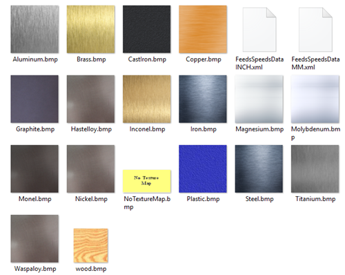
4.You will need to know the Surface Speed and Feed/Tooth specifications for each instance of the Material you are adding to the XML file. Here is the information format: 5.You need to make sure that you have the Units format specified correctly in your custom material XML files. It is defined on the 2nd line of the Materials XML file. For Inch units use <Units>Imperial</Units> and for Metric units use <Units>Metric</Units> as shown here for Inch: 6.There is also a bitmap image file (*.bmp) associated with each Material type defined in the XML file. This image defines the texture that is applied to the Stock material when the Toggle Material Texture Visibility icon is enabled. The image is also displayed in the Select Stock Material dialog.
|

Adding specific materials you use regularly in your shop to the Feeds & Speeds Calculator in VisualCAM can save toolpath programming time and help ensure cut surface quality and machining time accuracy. Just be sure to review this post carefully. A summary is also listed below. If you need help, you can always contact us at MecSoft Support via the phone, web or email. 1.You can select a Material to be applied to your Stock definition. 2.The selection of materials are retrieved from an external data file (example: FeedsSpeedsDataINCH.xml) located in the install path of VisualCAM on your computer. 3.The XML data file can be edited with any ASCII text or XML file editor. 4.The XML data file also contains information about the CAM Module, Tool Material, Surface Speed and Feed/Tooth for each instance of the material. 5.The stock material selected is used by the Feeds & Speeds Calculator to suggest Surface Speeds and Cut Feed Rates. 6.The Feeds & Speeds Calculator is displayed when you select Load from File from the Feeds & Speeds tabs of the Create/Select Tool dialog or from each toolpath operation dialog. 7.You can manually add more materials to the XML data file. You will need to know the recommended Surface Speed and Feed/Tooth specifications for the material you are adding based on each Tool Material type. 8.It is very IMPORTANT that you make a backup copy of these XML files if you plan to edit them. Also, the text format of the XML files is VERY IMPORTANT. If the format is incorrect, the Feeds & Speeds Calculator may not work properly! Make sure that the Units format on line 2 matches the Units you plan to use in your part files. 9.Each material also has a bitmap image texture file (*.bmp) that is located in the same folder. The material texture image is shown in the Select Stock Material dialog and is also applied as a texture map to your stock when the Toggle Material Texture Visibility icon is enabled. |