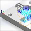
The following Cut Parameters tab allows you to define the cut parameters for the current Adaptive Roughing operation. You can set Global Parameters, Cut Pattern, and other options affecting the tool cutting paths.
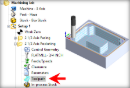
 Dialog Box: Cut Parameters tab, 3 Axis Adaptive Roughing |
 Global Parameters, 3 Axis Operations The Global Parameters section allows you to set the tolerance value to be used in machining. Intol and Outol are allowable deviations (tolerances) from the actual part geometry plus the Stock layer (if any). A uniform thickness or stock that needs to be left around the part can be specified here.
Intol / Outol
Inward tolerance - the maximum thickness of material that can be removed from the Stock layer. Outward tolerance is the maximum thickness of material that can remain above the Stock layer.
 Tolerances play a vital role in both design engineering and digital manufacturing. In design, the goal is to allow the broadest tolerance range possible while meeting your design specifications. This is because, generally speaking, there is a direct correlation between tighter tolerances and higher manufacturing costs. Tolerances play a vital role in both design engineering and digital manufacturing. In design, the goal is to allow the broadest tolerance range possible while meeting your design specifications. This is because, generally speaking, there is a direct correlation between tighter tolerances and higher manufacturing costs.
Read the full article...
|
|
Stock
The thickness of the layer that will remain on top of the part after the toolpath is complete. Roughing operations generally leave a thin layer of stock, but for finishing operations this value is zero.
|
This can be controlled by specifying either Climb (Down Cut) or Conventional (Up Cut).
") Climb |
") Conventional |
|
 One of the basic concepts to understand in any milling operation is Cut Direction. It can be characterized by how the flutes of the cutting tool engage the stock material and form the chip that is removed during cutting. In many of MecSoft CAM’s 2½ & 3 Axis toolpath strategies you will see that Cut Direction is defined by selecting one of three options, Climb, Conventional or Mixed. Let’s take a look at the characteristics of each option. One of the basic concepts to understand in any milling operation is Cut Direction. It can be characterized by how the flutes of the cutting tool engage the stock material and form the chip that is removed during cutting. In many of MecSoft CAM’s 2½ & 3 Axis toolpath strategies you will see that Cut Direction is defined by selecting one of three options, Climb, Conventional or Mixed. Let’s take a look at the characteristics of each option.
Read the full article...
|
|
|
 | Transfer Cut Control |
Use the following cut parameters for controlling the cutter during transfer motions.
Cut Lift
During the High Speed cut pattern use this parameter to lift the cutting tool during transfer motions. 0 (Zero) means that the tool will not list. Enter a positive value and the tool will lift this amount in +Z prior to executing a cut transfer motion.
Feedrate Factor
During the High Speed cut pattern use this parameter to control the feed rate when the cutting tool is lifting and plunging before and after each cut transfer motion. The value is a percentage of the Cut Feed (Cf) parameter for this operation (i.e., 50 = 50% of the (Cf) feed rate).
|
 Stepover Control, 3 Axis Operations This allows you to define the spacing between the cuts. Select from the following options:
% Tool Diameter
Enter the stepover distance as a percentage value of the tool diameter.
Distance
Enter the exact stepover distance preferred.
|
| Cut Arc Fitting |
Check this box to Perform Arc Fitting . The system will attempt to fit arcs along the computer toolpath if they lie within the three principal planes (XY Plane, XZ Plane or YZ Plane).
 Off |
 On |
|
|