The following Cut Parameters tab allows you to define the cut parameters for the current 5 Axis Surface Normal operation. You can set Global Parameters, Cut Traversal, Tool Axis Control, Cut Pattern and Stepover parameters via this tab of the operation dialog.
The Global Parameters section allows you to set the tolerance value to be used in machining. A uniform thickness or stock that needs to be left around the part can also be specified here. Refer to each option below.
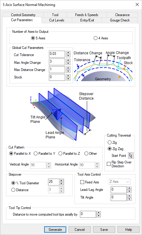 Dialog Box: Cut Parameters tab, 5 Axis Surface Normal Machining Operations |
This setting allows Premium configuration users to machine 5 Axis toolpaths in 4 Axis mode. This provides additional 5 Axis toolpath strategies for those who have a 4 Axis machine tool. The following 5 Axis strategies are supported in 4 Axis mode: 5 Axis Curve Projection Machining 5 Axis Flow Curve Machining 5 Axis Between 2 Curves Machining 5 Axis Surface Normal Machining 5 Axis Swarf Machining This example shown is a section of a complex wooden handrail. 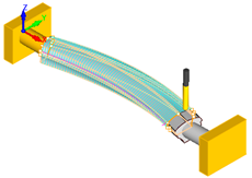 4 Axis Mode Machining Select from the following: 5 Axis The toolpath will be calculated in normal 5 Axis mode. Your Machine Definition should be set to 5 Axis. 4 Axis The toolpath will be calculated in 4 Axis mode. Your Machine Definition should be set to 4 Axis. |
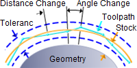 Global Cut Parameters This section of the Cut Parameters tab allows you to set the following parameters: Cut Tolerance This is allowable deviations (tolerances) from the actual part geometry plus the Stock layer (if any).
Max Angle Change his is the maximum allowable angle change between two toolpath points. Max Distance Change This is the maximum allowable distance change between two toolpath points. Stock The thickness of the layer that will remain on top of the part after the toolpath is complete. Roughing operations generally leave a thin layer of stock, but for finishing operations this value is zero. |
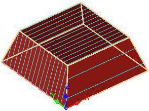
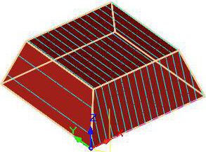
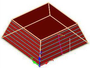
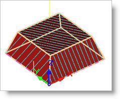
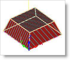
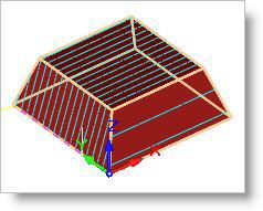
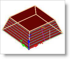
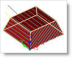
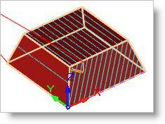
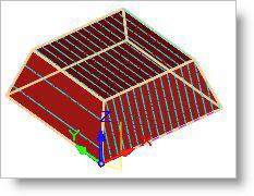
The cut pattern can be set parallel to X, Y, Z or by specifying Vertical Angle and Horizontal Angle values.
|
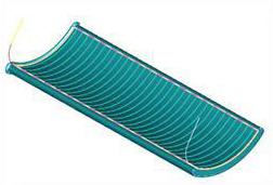
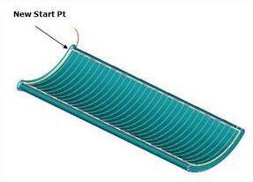
This section allows you to define the type of cut that the tool will follow. ZigZag The cutter traverses back and from along the cuts. Zig The cutter traverses the cuts in a single direction. Start Point Allows you to select a start point on the drive surface.
Flip Step over Direction Allows you to change the cut direction. |
This section allows you to define the spacing between the cuts. This can specified as Distance or % Tool Diameter. |
Fixed Axis For Tool Axis Control, check this box to control the tool axis during cut motions and then select either X Axis, Y Axis or Z Axis from the menu provided. This allows better control of the tool axis in tight spaces for simultaneous 5 Axis machining. Rotation Angle With Fixed Axis is checked, you can use this option to further control the tool axis by providing a maximum Rotation Angle. Lead/Lag Angle When Fixed Axis is not checked, this option controls the tool axis angle along the direction of travel. Tilt Angle This defines the direction normal to the direction of travel. |
For additional Tool Tip Control, you can specify a Distance to move computed tool tips axially. Specifying a value would move the computed toolpath axially by this specified value. |

