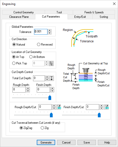
The following Cut Parameters tab allows you to define the cut parameters for the current 2½ Axis Engraving operation. You can set Global Parameters, Location of Cut Geometry and Cut Depth Control via this tab of the operation dialog. The Global Parameters section allows you to set the tolerance value to be used in machining.
 Dialog Box: 2½ Axis Engraving |
 Global Parameters, 2½ Axis V-Carving The Global Parameters section allows you to set the tolerance value to be used in machining. •Tolerance
|
Select from the following for the engrave Cut Direction: •Natural •Reversed |
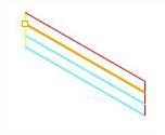
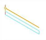
 Location of Cut Geometry, 2½ Axis V-Carving The cutter can be set to cut inside the curve or trace the outside of the curve. The Location of Cut Geometry can be set to At Top (top Z level), At Bottom (bottom Z level) or Pick Top (specifying the Z location) by entering a Z value location or by selecting the pick At Top This uses the Z location of the selected Machining Features/Region as the top of cut. The generated cuts will start at this Z location and cut down in Z to the specified total cut depth. At Bottom This uses the Z location of the selected Machining Features/Region as the bottom of cut. The generated cuts will be above the selected machining region and last cut would be at the Z location of the specified region. Pick Top This allows you to specify the Top of Cut for the selected Machining Features/Region and is typically used when the selected region is not at top or bottom. The generated cuts will start at this specified Z location and cut down in Z to the specified total cut depth. |
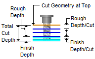
The Cut Depth Control enables you to define the depth of the cut. You can define a Rough Depth and a Finish Depth by either typing in the desired values or by using the slider bars provided. Similarly you can define the Depth per Cut for both the Roughing and the Finishing paths.
|
This can be set to Zig or ZigZag. Setting the cut traversal to Zig generates cuts along the direction of the curve, retracts the tool to cut transfer plane and starts at the same start location for the next level. Setting the cut traversal to ZigZag cuts both directions.
|


