The following dialog allows you to set the Cut Parameters for Boring operations. You can set the Bore Type, Depth Control, Location, Dwell and other parameters via this dialog box. The Bore parameter settings are similar to the Drill parameter settings. Just as in the Drilling operation, user defined Bore cycles can be created by selecting User Defined Bore under Bore Types.
 Cut Parameters tab, Boring, 2½ Axis |
The bore types supported are: Drag Bore The tool is fed to defined depth at the controlled feed rate; the spindle is stopped and then a rapid retract is performed.
No Drag Bore The tool is fed to the specified depth at the controlled feed rate. It is then stopped to orient the spindle, moved away from the side of the hole and finally retracted. Tool Orientation is supported. See Optional Parameters listed below. Manual Bore The tool traverses to the programmed point; feeds to the specified depth at the controlled feed rate; and then stops motion for a manual retract. User Defined Bore1 / User Defined Bore2 These are bore cycles that you can define using the User Defined Cycles in the Post-Processor Generator. |
Bore Depth refers to the hole depth. |
Select from the following for Location of Drill Point(s): At Top This uses the Z location of the selected Control Geometry as the top of cut. The generated cuts will start at this Z location and cut down in Z to the specified total Drill Depth. At Top is typically used when your hole diameters or drill points are at the top of your part. At Bottom This uses the Z location of the selected Control Geometry as the bottom of cut. The generated cuts will be above the selected machining region and last cut would be at the Z location of the specified region. At Bottom is typically used when you select the diameter or drill points are at the bottom of the hole. Project to 3D Model This option projects the selected the Control Geometry to the underlying 3D geometry. Pick
|
Dwell is an optional parameter that allows a machine delay of either Time (sec) Rev (rpm) of the spindle. |
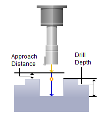
You can define the Approach Distance under Engage/Retract. The tool rapids in Z axis to the approach plane and applies the specified feedrate from the approach plane to the specified depth to perform the cycle. |
Tool Orientation |