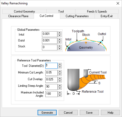
The following Cut Parameters tab allows you to define the cut parameters for the current 3 Axis Valley Re-Machining operation. You can set Global Parameters, Cut Direction and the Stepover Control via this tab of the operation dialog. The Global Parameters section allows you to set the tolerance value to be used in machining. A uniform thickness or stock that needs to be left around the part can also be specified here. Refer to each option below.
 Dialog Box: Cut Control tab, Valley Re-Machining, 3 Axis |
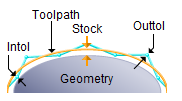
 Global Parameters, 3 Axis Operations The Global Parameters section allows you to set the tolerance value to be used in machining. Intol and Outol are allowable deviations (tolerances) from the actual part geometry plus the Stock layer (if any). A uniform thickness or stock that needs to be left around the part can be specified here.
Intol / Outol
Inward tolerance - the maximum thickness of material that can be removed from the Stock layer. Outward tolerance is the maximum thickness of material that can remain above the Stock layer.
 Tolerances play a vital role in both design engineering and digital manufacturing. In design, the goal is to allow the broadest tolerance range possible while meeting your design specifications. This is because, generally speaking, there is a direct correlation between tighter tolerances and higher manufacturing costs. Tolerances play a vital role in both design engineering and digital manufacturing. In design, the goal is to allow the broadest tolerance range possible while meeting your design specifications. This is because, generally speaking, there is a direct correlation between tighter tolerances and higher manufacturing costs.
Read the full article...
|
|
Stock
The thickness of the layer that will remain on top of the part after the toolpath is complete. Roughing operations generally leave a thin layer of stock, but for finishing operations this value is zero.
|
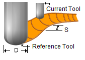
This section allows you to specify the reference tool diameter. This diameter must be larger than the current tool diameter.
 Reference Tool Parameters Tool Diameter (D)
Enter the reference tool diameter.
Minimum Cut Length
Ignore cuts lower than this length.
Cut Overlap
Set the overlap distance for successive passes.
Limiting Steep Angle
Additionally you can chose to ignore cuts steeper than a certain angle. This is usually done to avoid cutting very steep vertical areas in the part. The default value is 90 degrees, which means all cuts will be output. You need to specify something lower than this if he wants to prevent cutting very steep areas. This angle is also computed with respect to the XY plane.
Maximum Included Angle
You can also control the output of cuts based on the included angle. The included angle is the angle between the two tangent lines at the bi-tangency points of the pencil traces. Note that the re-machining cuts are the locations of all points where the tool is contacting the part-geometry in two or more tangential positions. Thus, the larger this angle the shallower this area. This angle has a range from 90 degrees to 180 degrees. At 90 degrees the tool is contacting at the side of a vertical wall. Close to 180 degrees the configuration of the two surfaces are quite shallow.
|


