The following Cut Parameters tab allows you to define the cut parameters for the current 4 Axis Drive Surface operation. You can set Global Parameters, Cut Pattern, Axial Containment and Stepover Control parameters via this tab of the operation dialog.
The Global Parameters section allows you to set the tolerance value to be used in machining. A uniform thickness or stock that needs to be left around the part can also be specified here. Refer to each option below.
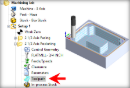
 Dialog Box: Cut Parameters tab, 4 Axis Drive Surface Operations |
 Global Parameters, 3 Axis Operations The Global Parameters section allows you to set the tolerance value to be used in machining. Intol and Outol are allowable deviations (tolerances) from the actual part geometry plus the Stock layer (if any). A uniform thickness or stock that needs to be left around the part can be specified here. Intol / Outol
Stock |
This section allows you to define the type of cut pattern that will be generated. You can also contain the toolpath both by specifying low and high values along the cut axis as well as by specifying a low and a high angular values about the rotation axis. Across Axis / Along Axis / Helix Selecting Along Axis will create toolpaths that traverse along the rotation axis. Selecting Across Axis will generate toolpaths that traverse perpendicular to the rotation axis. Selecting Helix will generate one toolpath that traverses along the rotation axis in a helical pattern. Each is illustrated below.
ZigZag / Zig Selecting ZigZag will allow the toolpath to traverse back and forth while the Zig option will force the toolpath to be in one direction only.
Clockwise / Counter Clockwise (for Helix option only) Selecting Clockwise will allow the toolpath to traverse in a Clockwise rotation (to the right when looking from the start point). Selecting Counter Clockwise will allow the toolpath to traverse in a Counter Clockwise rotation (to the left when looking from the start point).
Low To High / High To Low Selecting Low To High will make the toolpath start from the lower coordinate along the tool axis and proceed to the higher coordinate. Selecting High To Low will reverse this behavior.
Reverse Cuts This is a clockwise/counterclockwise control. If Along Axis is selected, the clockwise or counterclockwise can be turned on by checking this on or off. If Across Cuts is selected, then in each cut, clockwise or counterclockwise can be turned on by checking this on or off. Project to Geometry Check this box to project the toolpath to all visible surfaces. If left unchecked, no projection will take place and the toolpath will be gouge checked only against the drive surfaces listed in the Control Geometry tab of this dialog. |


This allows you to define the spacing between the cuts. Select from the following options: % Tool Diameter This allows you to set the stepover distance for the current operation as a percentage of the active tool diameter.  % Tool Diameter Distance Specify the stepover for the current operation as an exact Distance and then enter the distance value in the field provided. Distance |