Control Geometry refers to the part geometry that controls the current operation. 3 Axis operations can use 2D curves and 3D curves and surface edges as Control Geometry. For 3 Axis operations, Control Geometry is divided into three possible categories: Containment Regions, Part Regions, Part Surfaces and Start Points. The Control Geometry tab has sub-tabs for selecting each of these categories of geometry from your part.
|
|
|||||||||||||||||||||||||||||||||||||||||||||||||||||
 Dialog Box: Control Geometry tab, Horizontal Finishing, 3 Axis |
The Part Regions tab displays in all 2½ Axis and some 3 Axis operations. It is used to drive the tool during the operation. Use one of the Select... buttons in this dialog to add Part Regions to the Selected Machining Region(s) list. See Select Part/Containment Regions for more information.
|


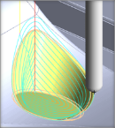
The Start Points tab allows you to specify a start point for the tool entry motion for pocketing and roughing operations. Selecting a start point applies the entry motion to the specified location.  Start Point Specified for 3 Axis Horizontal Finishing |
The Part Surfaces tab allows you to specify one or more 3D surfaces (or meshes) to machine in the current operation. No other containment regions are required. Use the Select Surfaces button to add part surfaces to the Selected Machining Region(s) list. See Select Part/Containment Regions for more information.
|

Move Up This button moves the selected item up (i.e., higher) in the list. Items are machined in the order listed. Move Down This button moves the selected item down (i.e., lower) in the list. Items are machined in the order listed. Remove All Pick this button to Remove All Regions from the list. The geometry itself is not deleted from the part model. Remove Active Pick this button to Remove the selected Active region from the list. You can select multiple Regions from the list using the Ctrl key and then pick this button to remove them all. The geometry itself is not deleted from the part model. Select Curve/Edge Regions Pick this button and the dialog will minimize, prompting you to make a selection from your part. You can select curves or face edges. After completing the selection, the dialog will re-appear with your Region selections listed. Select Surface Boundary Pick this button and the dialog will minimize, prompting you Select surface for boundary. You can select one or more part surfaces. After completing the selection, the dialog will re-appear with each surface edge boundary listed in the Selected Machining Region(s) list. Select Flat Area Regions Pick this button and you are prompted to make a selection from your part. You can select flat planar face geometry. After completing the selection, the dialog will re-appear with your region selections listed. Select Pre-Defined Regions If you pick this button, the Select Pre-defined Machining Regions dialog will display, allowing you to select one or more Regions. This operation dialog will then re-appear with your region selections listed. Pre-Defined Regions can be created using the options on the Regions tab of the Machining Objects Browser. See Predefined Machining Regions for more information. Select Surfaces Pick this button and the dialog will minimize allowing you to select part surfaces to machine. After completing the selection, this dialog will reappear with your selected surfaces listed in the Selected Machining Region(s) list. Select Start Points Pick this button to select Start Points for the operation. The dialog will minimize, prompting you to make a selection from your part. You can select either a point or a curve/edge. If you select a curve/edge, the Start Point of the curve/edge is used. After completing the selection, the dialog will re-appear with your Region selections listed. |