Available in: |
Xpress |
Standard |
Expert |
Professional |
Premium |
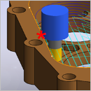
![]() This allows you to detect collisions between the selected Tool and the Part geometry based on the tool properties (tool length, diameter, holder length and diameter). This command is located on the Tools tab of the Machining Objects Browser.
This allows you to detect collisions between the selected Tool and the Part geometry based on the tool properties (tool length, diameter, holder length and diameter). This command is located on the Tools tab of the Machining Objects Browser.
|
1.From the Tools tab of the Machining Objects Browser, select the Compute Tool Holder Collisions button ![]() .
.
Note: The actual icons you see in this dialog will depend on what module and what configuration you are currently licensed to operate  From the Tools tab of the Machining Objects Browser, select the Compute Tool Holder Collisions button |
2.This brings up the Tool Holder Collision Areas dialog that indicates the default Tool dimensions for the active tool. You can change these values here for the purpose of calculating collisions. Any changes made here will not modify your tool parameters. You can also set the part clearance. Click Compute to determine any collision areas.
 the Tool Holder Collision Areas dialog |
3.A visual comparison of the tool holder collision model against the part model is displayed. You can color-code these areas based on the areas by depth of collision.
|

4.The system also indicates the minimum Tool Length required to avoid collisions.
|

|