Here is a list of things you should know when posting G-Code using a customized post created from the Post-Processor Generator in VisualCAM.
The Post Process Generator supports Algebraic Expressions in all input fields. Here are some guidelines for using expressions: 1.Each expression should be placed in ‘E{’, ‘E}’ tags. 2.In expression can be used next operations: -,+,/,*,^ 3.Negative values should be placed in parentheses '( )’ 4.Expression parts can be placed in parentheses '( )’ 5.Floating point numbers should be delimited by point symbol, use 0.xx in case of fractional numbers 6.Expressions can contain spaces in any place, spaces will be removed while parsing 7.Numbers in [-0.9; 0.9] can be written as [-.9; .9] Examples: •E{ ([SOME_VAR1]/2 + ([SOME_VAR]*(-3.2)) )^3 E} •E{[SOME_VAR1] + .3 E} SOME_TEXT E{ [SOME_VAR1] *(-1) E} |
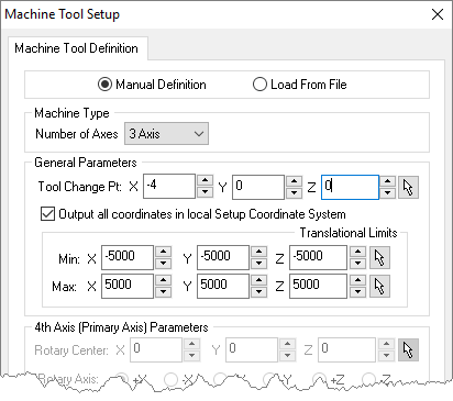
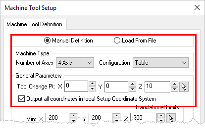
Drill cycles will be converted to simulated cycles (i.e., using linear motions) if the setup the drill cycles appear in is not aligned with the machine Z axis. This is done only when the machine has a head configuration defined and Output all coordinates in local Setup Coordinate System is not checked. See Machine Tool Setup for more information. |
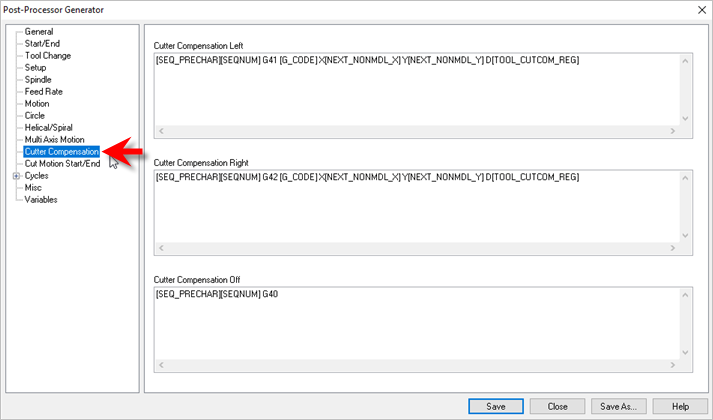
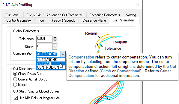
All toolpaths except engraving are automatically compensated for the tool geometry. Cutter compensation is used typically to compensate for the difference in the dimensions of the actual cutter used in machining and the cutter used for programming in VisualCAM. For example, if the cutter used in programming is 0.25 inches and due to tool wear the actual cutter is only 0.24 inches in size, you can compensate for this at the controller rather than having to re-program the operation in VisualCAM. Cutter compensation is used extensively in production (high volume) machining where the machine operator can compensate for tool wear before having to stop and replace the tool or insert. In order to do this the user needs to do the following: 1.Turn cutter compensation on in the operation to Auto/ON or CONTROL/ON. 2.Specify the cutter compensation value and the compensation register in the controller (the controller needs to be capable of doing this). 3.Please make sure the post processor is configured to output cutter compensation. This is defined under the Cutter Compensation section in the post processor generator. Most controllers expect an X & Y motion on the same line as cutter compensation.
A few things to watch out for: 1.Cutter compensation makes sense only in 2-1/2 axis operations. If you are using roughing (pocketing & facing) the compensation will be turned on only in the final passes. 2.Make sure you are using Climb or Conventional cut traversal in any of the methods that you want to turn compensation on.
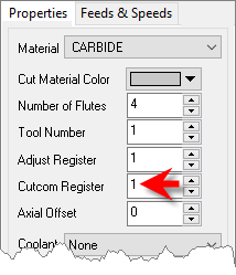
3.Make sure you have a linear motion for the controller to turn on the compensation for. If your first motion is an arc the controller will not be able to turn on the compensation. Thus, in 2-1/2 axis profiling, make sure there is a linear entry motion for the controller to be able to turn compensation on & linear exit to turn off compensation. If you are looking to compensate for the full tool diameter, set Stock = -0.125 under the cut parameters tab. (0.125 being the radius of the tool). This would generate the toolpath ON the curve. This would invalidate the simulation as the tool tip stays on the drive geometry. Note: The Cutcom Register is set under the Create/Select Tool definition dialog.
|
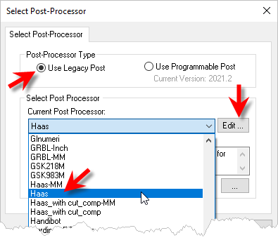
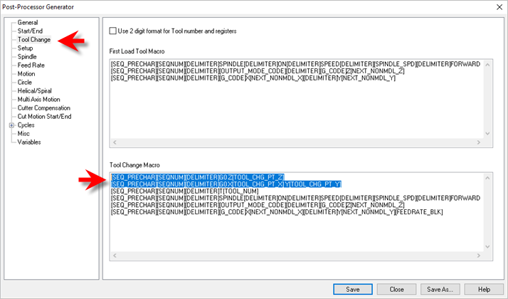
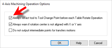
Implementing a Tool Change Point can be useful. For example in 2 and 3 Axis, you may want to change tools manually between operations (i.e., your CNC machine does not have an automatic tool changer). Also in 4 Axis you may want to ensure the tool is moved to a save location prior to a table rotation. To output a Tool Change Point to your posted g-code files, please do the following:
|
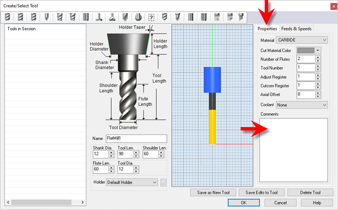
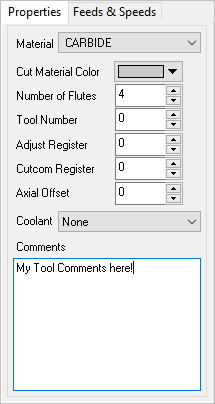
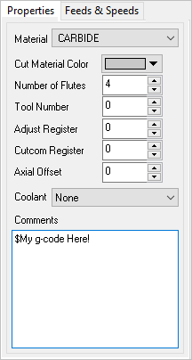
You can add comments associated with a Tool. These Comments are saved with the Tool in your Tool Library. They are also posted to your g-code when the tool is used. Here are the steps to add Comments to a Tool: 1.Edit the Tool using the Create/Select Tool dialog. 2.Select the Properties tab on the right.
3.Add text to the Comments window.
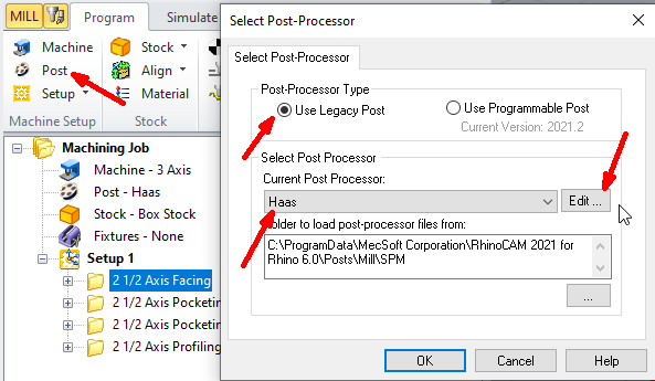
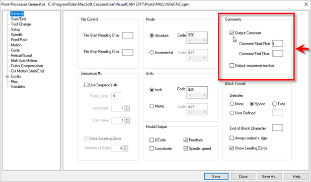
4.Make sure Comments are enabled in your post.
5.Now post your operations and see your comments:
6.If you want to post g-codes instead of comments, just place a $ character prior to the comment in the Create/Select Tools dialog. Adding $ as prefix will skip the comment start & end characters in the posted code.
|