Historically 2½ Axis operations have been typically used with curves as the control geometry and the underlying 3D model is implied by the curves selected. However, with the advent of solid modeling systems, 2½ Axis operations can be utilized more effectively by CAM systems by utilizing the intelligence already built into the 3D model, rather than having to derive it from just curves. There are three separate areas where cutting information can be derived from 3D models. These are:
1.Automatic detection of Total Cut Depth.
2.Automatic detection of a height when Location of Cut Geometry is At Bottom.
3.Automatic detection of Cut Start Side in Profile operations.
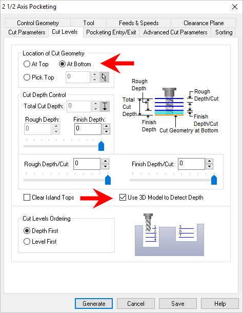
The total cutting depth can be derived from the 3D model rather than having to input this value by measurement. In addition to efficiency, this feature allows for automation of machining. To utilize this feature, check the called Use 3D Model to compute Depth. This parameter can be found on the Cut Levels tab of most 2½ Axis operations.  Dialog Box: Cut Levels tab, MILL Operations Setting this parameter will allow the system to calculate the depth of cut needed by examining the pocket or profile region selected by the user in relation to the 3D model.
|
This section describes the typical use cases for this parameter setting. •Pockets and profiles with a single flat bottom.
•Pockets and Profiles with single flat bottoms but with different depths. Both hole pocketing and regular pocketing can be used for machining.
•Outside Profiles. In such cases the system will compute the bottom most point of the 3D model as the last cut level.
•Stepped Pockets & Profiles: In such cases the cutter will stop at the highest step and will not go down any further.
|
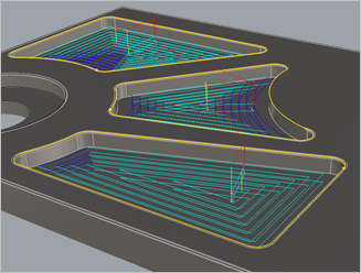
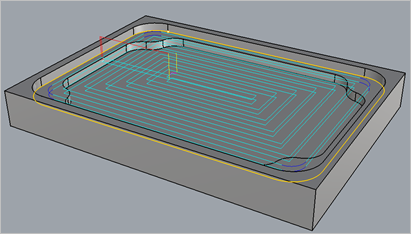
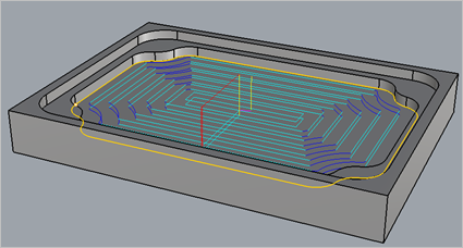
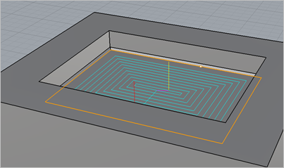
Another useful scenario under which this feature can be used is when you select a flat area that is the bottom of a pocket as the control geometry. You can then choose to specify the location of control geometry to be At Bottom. If you have checked Use 3D Model to compute Depth, then the system will automatically compute the height of the wall of the pocket to start cutting from. Refer to the dialog and example shown below:
The system uses the 3D model and computes the height of the wall around the flat area selected and begins cutting from that level. This can be seen by the multiple z levels computed in the toolpath example.
|

The detection of cutting depth is not a fool proof algorithm and there are cases where this parameter cannot be applied successfully. This section describes these cases. •When you have a chamfer or fillet at the floor of the pocket, or a sculpted surface bottom in a pocket this method cannot be used to determine the depth correctly. Different strategies need to be employed to machine such geometrical conditions.
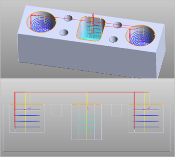
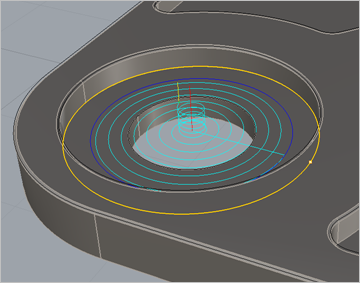
•Pocketing of stepped pockets, including stepped holes as seen below cannot be cut with a single operation. These need to be programmed in multiple stages, one program for each step.
•Determine using 3D model does not work for 4 Axis Facing, Pocketing or Profiling operations.
|
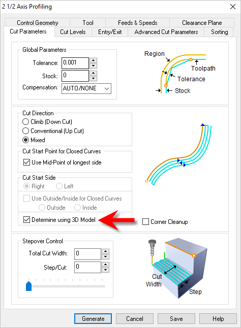
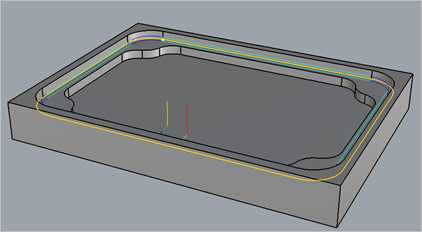
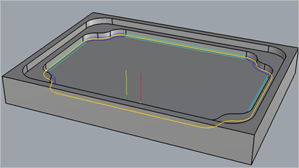
Another useful scenario under which information from 3D models can be utilized is in determining the cutting side of a control curve in 2½ Axis Profile machining. You can choose to automatically compute the side where the cutter should cut by selecting Determine Using 3D Model from the Cut Parameters tab shown below:
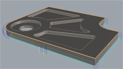
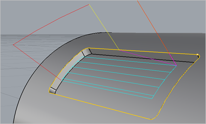
An example is shown below. Here the highlighted curve is selected as the control geometry and under the Cut Start Side section of the dialog, Determine using 3D Model is checked. This results in the toolpath being generated on the correct side of the selected curve as shown in the example below:
|