The 5 Axis Drive Curve (Follow curve) Machining operation requires you to select Drive Curves as control geometry. See Control Geometry for more information regarding feature/regions.
Drive surfaces are the model geometry which is used for tool path generation; it is the surface you want to work on and defines the shape to be milled. You can select multi surfaces. Drive surfaces determine the tool location and tool axis in some cases.
|
Drive curves are used to control the cutter locations. Here you select one or more curves as drive curves and the tool will follow the curve and these curves will be projected onto the Drive surfaces. The tool positions will then be modified according to gouge checking on the part surfaces.
|
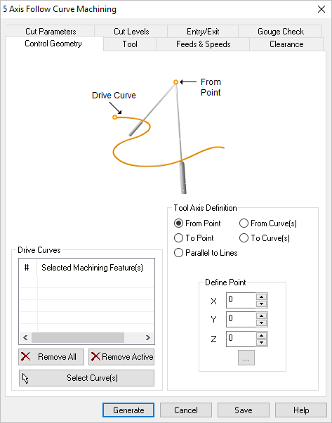 Dialog Box: Machining Features tab, 5 Axis Drive Curve Operations |
In this section of the Machining Features tab, you select one or more drive curves to control the cutter locations. The tool will always follow the curve.
Select Curves(s)
Selecting this button minimizes the dialog and prompts you to select curves. To end the selection press the enter key on the keyboard or right mouse button click. The selected curves are displayed under Selected Machining Feature(s) list. Selecting a Region from the list highlights the geometry on the graphics area.
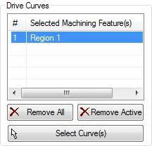 Drive Curve(s), dialog |
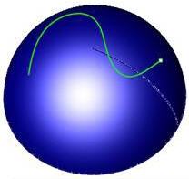 Drive Curve(s), highlighted |
Remove All
This removes all selected surfaces from the Selected Machining Feature(s) list.
Remove Active
This allows you to remove a region from the selection list. You need to select a region from the list of Selected Machining Feature(s) and click Remove Active or press the delete key on the keyboard.
|
The tool axis for each cutter location point can be defined by one of the following methods:
This option creates the tool axis vector from a selected point. The tool moves appear as if the tool was originating at the point. You have the option of entering the X,Y,Z coordinate values or you can select the ... button to select a point from the model.
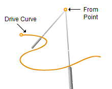 Tool Axis Definition = From Point |
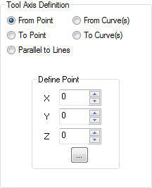 Tool Axis Definition, dialog |
|
This option creates the tool axis vector to a selected point. The tool moves appear as if the tool was pointed towards the point. You have the option of entering the X,Y,Z coordinate values or you can select the ... button to select a point from the model.
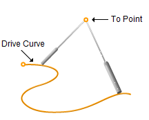 Tool Axis Definition = To Point |
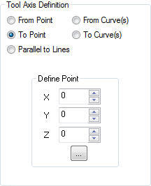 Tool Axis Definition, dialog |
|
This option sets the tool axis parallel to the selected Tilt Lines along the drive curve. Multiple lines can be selected to define the toolpath. The tool axis will be interpolated between the lines along the curve in sections of the curve between each pair of lines.
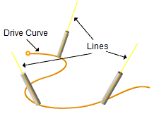 Tool Axis Definition = Parallel to Lines |
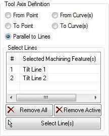 Tool Axis Definition, dialog |
Click Select Line(s) to select Tilt Lines. Selecting this button minimizes the dialog and prompts you to select lines. To end the selection press the enter key on the keyboard or right mouse button click. Selected lines are displayed under Selected Machining Feature(s) list. Selecting a Tilt Line from the list highlights the geometry on the graphics area.
|
This option creates the tool axis vector from the selected curve. The tool moves appear as if the tool was originating from the curve to the drive curve.
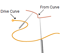 Tool Axis Definition = From Curve(s) |
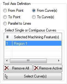 Tool Axis Definition, dialog |
Click Select Curve(s) to select. Selecting this button minimizes the dialog and prompts you to select curves. To end the selection press the enter key on the keyboard or right mouse button click. Selected curves are displayed under Selected Machining Feature(s) list. Selecting a Region from the list highlights the geometry on the graphics area.
|
This option creates the tool axis vector to the selected curve. The tool moves appear as if the tool was directed towards the curve from the drive curve.
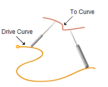 Tool Axis Definition = To Curve(s) |
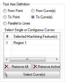 Tool Axis Definition, dialog |
Click Select Curve(s) to select. Selecting this button minimizes the dialog and prompts you to select curves. To end the selection press the enter key on the keyboard or right mouse button click. Selected curves are displayed under Selected Machining Feature(s) list. Selecting a Region from the list highlights the geometry on the graphics area.
|
|


