Once part geometry is loaded, user can set the cutting direction. This orients the Machine Coordinate System for Turning to have the part aligned in the same way as it would be fixtured on the machine tool for cutting. The stock geometry and machine tool definition will be defined based on the orientation of the machine tool coordinate system.
This dialog offers a convenient way of aligning the Machine Coordinate System (MCS).
 Dialog Box: Machine Tool Setup, Machine Tool Coordinate System tab |
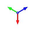
The Machine Coordinate System (MCS) is displayed as a triad with Blue line representing the Z-axis, Red representing X-axis and Green representing the Y-axis. The WCS is displayed the same way as MCS and is located at the origin. The lengths of the WCS arrows are shorter when compared to MCS.
|
")
")
This aligns the MCS orientation. Select from the following:
|
Allows you to set the Machine Coordinate System parallel to the World X Y or Z co-ordinate axis. •World X •World Y •World Z
|
|||||||||||||||||||


Allows you to rotate the Machine Coordinate System in X Y Z coordinate axis by any angle specified under Spin Angle. Specify Spin Angle and click the axis to rotate about. Clicking the same coordinate axis button multiple times rotates by the specified angle incrementally. For example if you set the Spin Angle = 90 and click X Axis button 2 times, the MCS is rotated about X coordinate axis by 180 degrees. |
This translates the MCS origin to the desired location. This can be set to any location on the part geometry. |
Resets MCS orientation to current MCS orientation. |