Cutter compensation is used typically to compensate for the difference in the dimensions of the actual cutter used in machining and the cutter used for programming in TURN Module. For example, if the cutter used in programming in TURN Module has a tool nose radius of 0.02 inches and due to tool wear the actual tool nose radius is only 0.01 inches in size, you can compensate for this in the controller rather than having to re-program the operation in TURN Module again.
To enable Cutter Compensation in your toolpaths: 1.On the Global Parameters tab of the Turn operation, set Compensation to Auto/ON. 2.Set Adjust Register and Cutcom Register from the Parameters tab of the Create/Edit Tools dialog box. 3.Enable Cutter Compensation in your Post Processor (see below). |
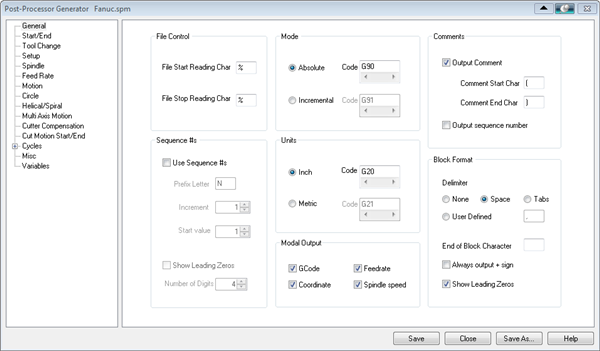
Specify the Cutter Compensation value and the Compensation Register in the controller (the controller needs to be capable of doing this). 1.From the Program tab of the Machining Browser, select 2.From the Set Post-Processor dialog box, select the Edit ... button located to the right of the Current Post Processor. 3.Enable Cutter Compensation from the Tool Change tab of the Post processor Generator dialog box. 1.From the Machining Browser, select 4.Select the Post Processor and then pick Edit. 5.Enable Cutter Compensation from the Tool Change tab of the Post processor Generator dialog box.
|
|
