The following Cut Parameters tab allows you to define the cut parameters for the current 4 Axis R-Level Finishing operation. You can set Global Parameters, Cut Direction, and the Cut Containment parameters via this tab of the operation dialog. The Global Parameters section allows you to set the tolerance value to be used in machining. A uniform thickness or stock that needs to be left around the part can also be specified here. Refer to each option below.
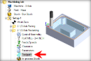
 Dialog Box: Cut Parameters tab, 4th Axis R-Level Finishing Operations |
 Global Parameters, 3 Axis Operations The Global Parameters section allows you to set the tolerance value to be used in machining. Intol and Outol are allowable deviations (tolerances) from the actual part geometry plus the Stock layer (if any). A uniform thickness or stock that needs to be left around the part can be specified here. Intol / Outol
Stock |
The Cut Direction of the toolpath can be specified either as Climb, Conventional or Climb/Conventional by selecting the appropriate radio buttons. In Climb or Conventional, the direction of cutting is maintained so as the corresponding cutting condition is maintained on the part. In the Climb/Conventional type of machining however, the direction of cutting is alternated between each parallel plane.
|


 One of the basic concepts to understand in any milling operation is
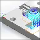
 You can also contain the toolpath both by specifying Low Value (L) and High Value (H) values along the cut axis as well as by specifying a Start Angle (S) and End Angle (E) values. The location of the Cut Containment planes are displayed in the graphics window. Note that these settings are ignored if machining regions are selected using the Control Geometry tab of the dialog.  Cut Containment Indicators Low Value (L) / High Value (H) Entering values for these two settings will contain the cutting within these two locations. Cutting will not be perform below the Low Value (L) location or above the High Value (H) location. These distances are measured from the MCS and along the rotation axis. Refer to the illustrations above. Start Angle (S) / End Angle (E) Entering values for these two settings will contain the cutting within these two locations. Cutting will not be perform below the Start Angle (S) and above the End Angle (E) positions. These angles are measured from the MCS and about the rotation axis. Refer to the illustrations above.
|