5 Axis Curve Projection Machining operations require you to select Drive Surfaces and Drive Curves as control geometry. See Control Geometry for more information regarding feature/regions.
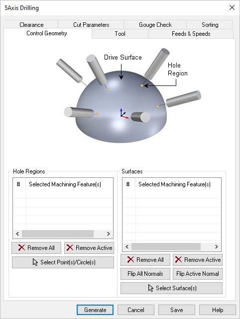
 Dialog Box: Control Geometry tab, 5 Axis Drilling Operations |
In this section on the Control geometry tab, you select one or more hole regions. In 5 Axis, hole regions are points that define the center of the hole to be drilled. Select Curve(s) This allows you to select curve or surface edges as drive curve. Selecting this button minimizes the dialog and prompts you to select curves. To end the selection press the enter key on the keyboard or right mouse button click. Remove All Removes all selected curves from the Selected Machining Feature(s) list. Remove Active This allows you to remove a region from the selection list. You need to select a region from the list of Selected Machining Feature(s) and click Remove Active or press the delete key on the keyboard. Select Points/Circles(s) You must select points to locate the Drilled holes. Also, these points must lie on the surfaces selected in the Surfaces portion of this dialog. Circles do not in 5 axis drilling so only select points as shown in the dialog icon. |
In this section of the dialog, you must select one or more surfaces. This surface(s) will define the drilling axis. Each point listed in the Hole Regions list (see above) will be projected normal to (i.e., perpendicular to) to surface(s) in this list. The selected surface(s) are displayed under Selected Machining Feature(s) list. Selecting a surface from the list highlights the geometry on the graphics area and displays the surface normal. Select Surface(s) Selecting this button minimizes the dialog and prompts you to select surfaces. To end the selection press the enter key on the keyboard or right mouse button click.
Remove All Removes all Selected Surfaces from the Selected Machining Feature(s) list. Remove Active This allows you to remove a region from the selection list. You need to select a region from the list of Selected Machining Feature(s) and click Remove Active or press the delete key on the keyboard. Surface Normals Tool path orientation is determined by the surface normal direction. So if you have generated the tool path on the wrong side you can simply change the surface normal by flipping the surface normal and regenerate your tool path again. The surface normal for each surface is represented by a green arrow on the surface. Flip All This flips the surface normals of all surfaces selected as Machining Features. Flip Active This flips the surface normal of the selected surface under Machining Region.
|