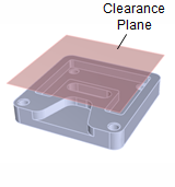
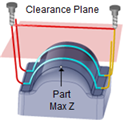
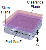
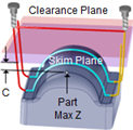
The clearance plane is an XY plane wherein all transfer motions between a retract and engage motion takes place. In the case of 4 axis operations, the clearance plane is a cylinder and defined along the axis of rotation. Typically you would define this plane at a certain safety distance above the part geometry. This is done to prevent the tool from touching the part being machined during transfer motions since these motions usually use a very fast or rapid feed rate.
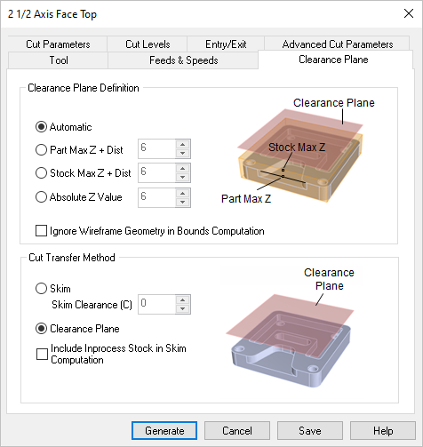 Dialog Box: Clearance Plane tab, 3 Axis |
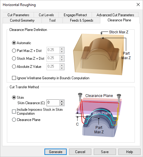 Dialog Box: Clearance Plane tab, similar for all Milling operations |
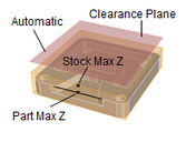
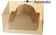
This selection defines the Clearance Plane for the current toolpath operation. Automatic Allow the system to calculate a the clearance plane height automatically based on the part and stock geometry.
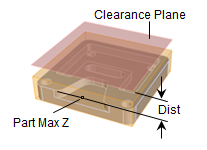
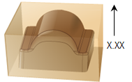
Part Max Z + Dist Set the Clearance Plane height to the maximum Z height of the Part plus this added distance.
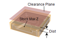
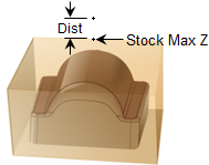
Stock Max Z + Dist Select this option to use the Stock's Maximum Z height and then enter a Distance value to add to this for the total Z height for the Clearance Plane.
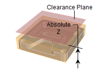
Absolute Z Value Select this to specify the absolute Z clearance height to use and then enter Z height value. Be sure that the value you specify clears your part geometry.
Ignore Wireframe Geometry in Bounds Computation Check this box to ignore all wireframe geometry when calculating the Clearance Plane definition. When checked, the Automatic and Part Max options for defining the Clearance will be calculated from actual surface geometry. 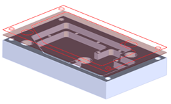 Ignore Wireframe Geometry in Bounds Computation |
This section allows you to control the tool's motions when it needs transfer to another region to begin cutting. Clearance Plane Select this option to move the tool to the Clearance Plane and then perform the Transfer motion to the next cut location.
Skim Select this option to perform transfer motions at a Skim plane. The system automatically determines a safe height and then adds this Skim Clearance (C) to the computed Z value to perform the Transfer Motions.
Include Inprocess Stock in Skim Computation When checked, the Skim Clearance (C) will account for the in-process during each transfer motion. 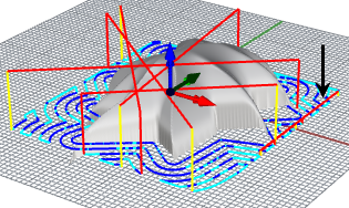 Include Inprocess Stock in Skim Clearance Computations This options (Include Inprocess Stock in Skim Computation) in only available in the following toolpath operations: •Re-machining (2 Axis) •Horizontal Roughing (3 Axis) •Plunge Roughing (3 Axis) •Horizontal Re-Roughing (3 Axis) •Plunge Re-Roughing (3 Axis) |
When the clearance plane dialog is active, specifying a clearance plane definition, displays the clearance plane on the part in the view port. 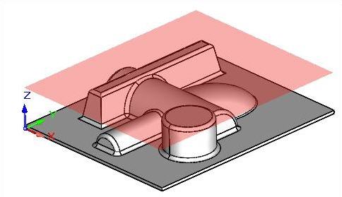 Display of Clearance Plane for Milling operations |
