The clearance plane is a plane from which the approach motions start and retract motions end. After retracting, the tool moves rapidly along this plane to the position of the next engage. This plane is typically a certain safe distance above the part geometry. Typically you would define this plane at a certain safety distance above the part geometry. This is done to prevent the tool from touching the part being machined during transfer motions since these motions usually use a very fast or rapid feed rate.
By default (Automatic option), the clearance level is calculated by adding a safety distance to the extreme point (depending whether Outer Diameter, Inner Diameter or Face is machined) found on both part and stock geometry. You can set the clearance level to be a set distance from either the part or stock, or enter the absolute Z level.
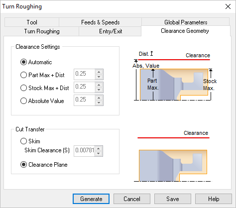 Dialog Box: Clearance Geometry for Turning operations |
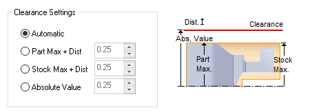 Turn OD Clearance |
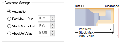 Turn Face Clearance |
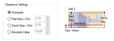 Turn ID Clearance |
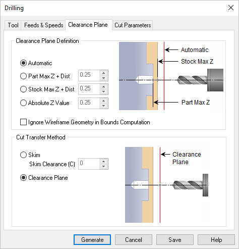 Dialog Box: Clearance Plane tab, Turn Reverse Boring |
Automatic The system determines the clearance height based on the part and stock geometry. Part Max + Dist Uses Part maximum plus the specified distance for clearance height. Stock Max + Dist Uses Stock maximum plus the specified distance for clearance height. If stock geometry does not exist, it would use the maximum height of the part geometry. Absolute Value Uses the specified distance for clearance height.
|
You can also control the transfer motions during cutting. When the cutter has finished cutting in one region and needs to transfer to another region to begin cutting, it can either be instructed to move to the clearance plane and then perform the transfer motion to the next cut location or it could do a skim motion. In the skim motion, the system automatically determines the safe height by taking into consideration the condition of the part model and using this Skim Clearance (S) value specified as the height to perform the transfer motions. |
 Cut Transfer Skim |
 Cut Transfer Clearance Plane |
When the clearance plane dialog is active, specifying a clearance plane definition, displays the clearance plane on the part in the view port. 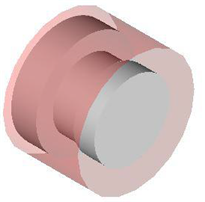 Clearance Plane for Turn OD operations |
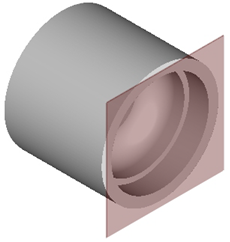 Clearance Plane for Hole Machining operations |