![]() You can define the raw stock model as a simple box by selecting the Box Stock option from the Stock menu under the Program tab in Machining Browser.
You can define the raw stock model as a simple box by selecting the Box Stock option from the Stock menu under the Program tab in Machining Browser.
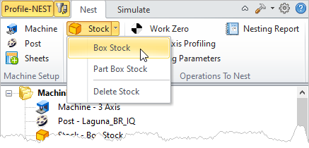 Machining Browser: Box Stock menu item |
Use this dialog to define your box stock. Corner position and dimension parameters are provided. Refer to the parameters below. When you pick OK, a stock model based on your definition will be created and displayed. 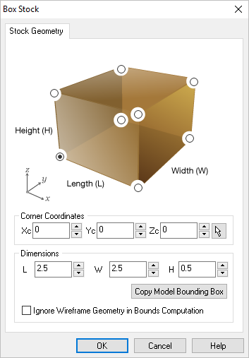 Box Stock Dialog |
Select a location from the dialog image to use as the origin to measure your stock from. For example: Set the Bottom South West corner of the Stock should serve as the origin to measured from. The Stock shown on your display will dynamically update accordingly. 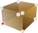 Bottom SW |
Alternatively, you can enter the world coordinates to determine where the corner of the Stock Box should be located. Your Stock Dimensions will be measured from this coordinate point (Xc, Yc, Zc).
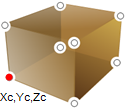 Stock Corner Coordinates |
You can use these fields to enter the Length (L), Width (W) and Height (H) of your desired Box Stock. 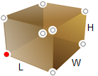 Stock Dimensions |
This button only calculates based on the sheet size, not part geometry. Make sure you have defined a sheet first using the Select Sheets dialog. The system calculates the bounding box extents of the sheet length, width and height and displays these values in the dialog. |
If you check the box Ignore Wireframe Geometry in Part Bounds Computation, any wireframe geometry in your part will be ignored when calculating the Part Bounds. Make sure to click Copy Model Bounding Box after you check or uncheck Ignore Wireframe Geometry in Bounds Computation. |