![]() Select this icon to perform Automatic Feature Machining (AFM) on your machining features. This command will create and generate toolpaths Automatically! You will need to perform (AFD) or (IFD) before running this command. Read the following information:
Select this icon to perform Automatic Feature Machining (AFM) on your machining features. This command will create and generate toolpaths Automatically! You will need to perform (AFD) or (IFD) before running this command. Read the following information:
|
The following will occur when you select this icon: 1.Automatic Feature Detection (AFD) is performed on all features listed in your Features Tree. 2.Toolpath Mops (Machining Operations) are created from matching operations in your default (AFM) Knowledge Base defined in the Features section of the CAM Preferences dialog. 3.Each Mop is added to your Machining Job tree and then regenerated automatically. |
You will need to do the following before running this command. Items 1 and 2 only need to be performed once. Items 3 and 4 are performed for each part you want to program using (AFM). 1.You will need to create and save your (AFM) Knowledge Base. See Create Machining KB for Milling Features and Create Machining KB for Selected Hole Feature. 2.Go to the Features section of the CAM Preferences dialog. and select your default Automatic Feature Machining (AFM) Knowledge Base. 3.NOTE: You MUST have a poly-surface model (i.e., a solid) in order to extract machining features. If you have an open surface model, you must stitch/join to close it before performing AFD. 4.You will need to perform (AFD) 5.To speed up toolpath generation time, go to the Machining section of the CAM Preferences dialog and make sure Always generate toolpath in multiple threads is checked (your PC should have a Multi-Core processor to take advantage of this feature). |
Here is an example of (AFM) being used to automatically program toolpaths for a 3D solid model: 1.An (AFM) Knowledge Base was created and saved. When loaded into the K-Bases tab, it looks like this. The Selection Rules are set to Features Types for each operation. The Create Machining KB for Milling Features command and the Create Machining KB for Selected Hole Feature command were used to define the milling and drilling operations.
2.The Default (AFM) Knowledge Base was defined in the Features section of the CAM Preferences dialog.
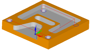
3.My part is opened. It is a 3D solid model and looks like this:
4.From the Features tab, the Automatic Feature Detection (AFD)
5.The part file now looks like this with the Machining Features highlighted:
6.From the Features tab, the Automatic Feature Machining (AFM)
7.The following toolpaths are generated automatically for my 3D solid model:
8.The cut material simulation looks like this:
9.A Part Box Stock was also created automatically because one was not defined when I ran the (AFM) command! |
 Knowledge Base loaded into the K-Bases tab")


 is performed with the Machining Features highlighted")


In AFM, the detected hole features in your part model will be paired with Hole Feature MOpSets defined in your default AFM Knowledge Base. This pairing is performed based on the detected hole feature's cross-section. See Hole Feature Cross-Section Rules. These rules are applied when a detected hole feature's cross-section varies from those found in the Default AFM Knowledge Base. The following is supported: 1.For Matching Holes 2.For Similar Holes a.For exactly matching segments, use the operation as is. b.For segments with different diameters, a tool from the tool library that has the same dimensional relationship as the tool in the KB has to the segment selected for machining in the KB. c.For segments with different depths, modify the Z depths to match the Z depth of the segment picked. |