Implementing a Tool Change Point can be useful. For example in 2 and 3 Axis, you may want to change tools manually between operations (i.e., your CNC machine does not have an automatic tool changer). Also in 4 Axis you may want to ensure the tool is moved to a save location prior to a table rotation. To output a Tool Change Point to your posted g-code files, please do the following:
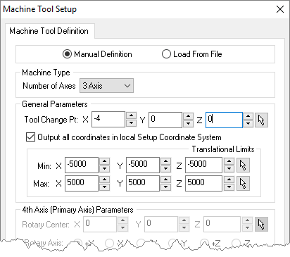
1.From the Machine Setup dialog (Program tab > Machine > General Parameters > Tool Change Pt), enter your required tool change point coordinates. 2.For the sample code (shown at the end of this section) we entered the following values in the Machine Setup dialog:
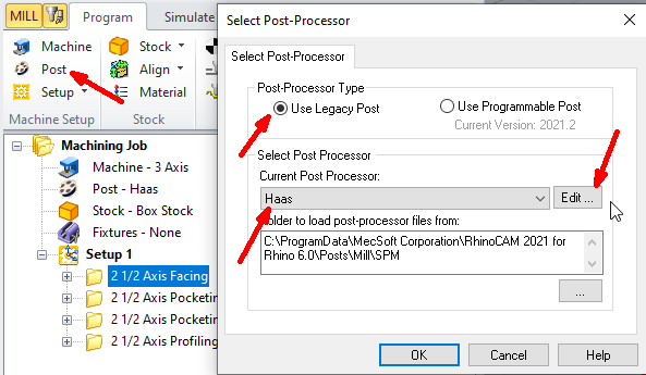
3.Edit your post processor by selecting Program tab > Post > Edit.
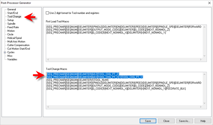
4.From the Post Process Generator dialog, select the Tool Change section from the left side of the dialog. 5.In the Tool Change Macro block section, replace the first line of text with the following two lines of text at the top of the macro.
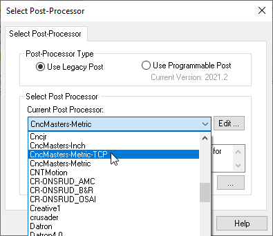
6.If your controller expects to see an optional stop call BEFORE each tool change, you can add another line like below: 7.From the Post Process Generator dialog, pick Save As. 8.Enter a unique name for your post file (*.spm) for testing and pick Save. 9.From the Set Post-Processor Options dialog, select the revised post from the Current Post Processor list.
10.Note: If you do not see your revised post in the list, select the "..." button to the right of the "Folder where post-processor file are located" and select the folder where you saved your revised post file to (see Step 7 above) and pick OK. 11.You should now see your revised post in the list. Select it and pick OK. 12.Post a sample toolpath using the revised post. 13.Review the g-code test file and locate the first tool change lines of code. 14.Your sample test should look something like this depending on your post (based on the tool change point we used in Step 2 above). Note the tool change coordinates in blue: 15.That's it! |
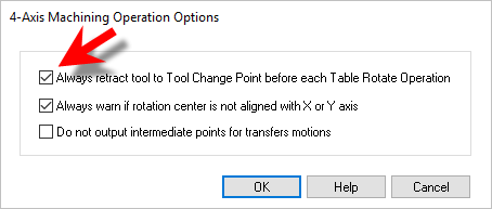
1.From the Program tab select 4 Axis. 2.From the 4 Axis menu select 4 Axis Options. 3.From the 4 Axis Operation Options dialog check the box to Always retract tool to Tool Change Point before each Table Rotate Operation.
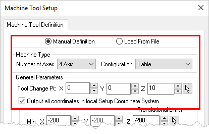
4.Now from the Program tab select Machine and then Manual Definition. 5.For the Machine Type select 4 Axis. 6.Under General Parameters, enter the X, Y and Z coordinate values for the Tool Change Point.
7.Then check the box to Output all coordinates in local Setup Coordinate System and then pick OK to close the dialog. 8.Post the 4 Axis toolpath operation and verify that the Tool Change Point is being posted before the table rotation angle similar to this: |